
 WhatsApp: +86 16626708626
 Email:
  Phone: +86 16626708626
Description
3. Key Technical Specifications
| Parameter | Value |
|---|---|
| Model Number | DS3800HXTA |
| Manufacturer | GE General Electric |
| Series | Speedtronic Mark IV DS3800 |
| Product Type | Series 6 Transmitter Board |
| Primary Function | Signal transmission and rack communication |
| Application | Gas and Steam Turbine Control |
| Compatible Systems | GE Mark IV Control Platforms |
| Communication Method | Proprietary GE backplane interface |
| Mounting Style | Rack-mounted PCB |
| Connector Type | Modular edge connector |
| Retention Hardware | Dual retention levers |
| PCB Protection | Industrial conformal coating |
| Operating Temperature | 0 °C to +50 °C typical cabinet environment |
| Storage Temperature | −40 °C to +85 °C |
| Humidity Rating | 5% to 95% non-condensing |
| Typical Cabinet Voltage | 24 V DC control environment |
| Product Status | Legacy / Obsolete Hardware |
| Availability | Surplus and refurbished inventory only |
4. Product Introduction
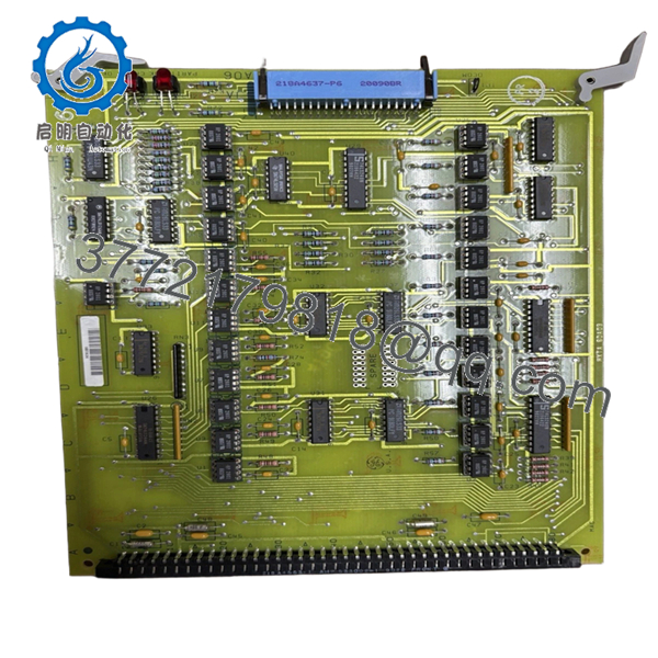
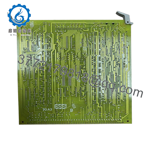
The GE DS3800HXTA is a Series 6 Transmitter Board used in GE Speedtronic Mark IV turbine control systems for rack-level communication and signal transmission functions. It operates inside legacy gas and steam turbine control cabinets where reliable backplane communication remains critical for startup sequencing and protection logic.
In field maintenance work, this board is commonly replaced during Mark IV lifecycle support projects where aging transmitter circuitry, intermittent communication faults, or unstable rack synchronization begin causing nuisance alarms or startup delays. Plants maintaining Mark IV systems generally choose direct replacement hardware to avoid major migration downtime and engineering costs.
5. Installation & Configuration Guide
Stage 1: Pre-Installation Preparation (Estimated Time: 10 Minutes)
⚠️ Safety First
- Notify plant operations before removing the turbine control cabinet from service.
- Verify the turbine is fully shut down and isolated.
- Apply lockout/tagout procedures to all cabinet power sources.
- Wait at least 5 minutes for capacitor discharge before touching internal hardware.
Tools Required
- ESD wrist strap
- PH1 screwdriver
- Fluke 115 multimeter
- Wire labels
- Smartphone for reference photos
- Flashlight for rack inspection
Data Backup
- Backup all available Mark IV configuration files.
- Record the exact rack slot location.
- Photograph:
- Connector orientation
- Jumper positions
- Cable routing
- Existing LED states
❗Take photos before disconnecting anything. I have seen technicians reinstall these older DS3800 boards one slot off and spend an entire outage chasing communication faults that were entirely mechanical.
Stage 2: Removing the Old Module (Estimated Time: 5–10 Minutes)
- Open the Mark IV cabinet front access panel.
- Label all attached cables before removal.
- Disconnect wiring carefully without twisting the PCB.
- Release retention levers and mounting hardware.
- Pull the board straight outward to avoid damaging edge connectors.
- Inspect:
- Backplane connector pins
- Dust accumulation
- Oxidation
- Heat discoloration
⚠️ Note
Do not discard the original board until startup testing is complete. Legacy GE systems often contain undocumented field jumper modifications.
Stage 3: Installing the New Module (Estimated Time: 10 Minutes)
- Wear a grounded ESD wrist strap before handling the replacement PCB.
- Verify the exact model number: DS3800HXTA.
- Inspect the replacement board for:
- Connector damage
- Cracked solder joints
- Corrosion
- Shipping damage
Configuration Clone (Crucial)
- Replicate all jumper and hardware settings from the original board.
- Verify connector orientation before insertion.
- Check rack guide alignment carefully.
❗This is one of the most common mistakes with Mark IV hardware. Someone assumes the replacement board ships correctly configured from stock. It usually does not.
I once watched a maintenance crew lose nearly eight hours because a replacement DS3800 board shipped with default jumper settings that did not match the plant rack addressing.
- Slide the board evenly into rack rails.
- Press firmly until fully seated.
- Secure retention hardware evenly.
- Reconnect all cables and verify strain relief.
Self-Checklist
- Jumpers match original
- Connectors fully seated
- Rack tabs locked
- No loose wiring
- Board aligned correctly
Stage 4: Power-On & Testing (Estimated Time: 10–15 Minutes)
Pre-Power Check
- Verify no shorts exist on cabinet DC rails.
- Confirm grounding continuity with a multimeter.
- Inspect edge connector engagement carefully.
Power-On Steps
- Energize the Mark IV rack only.
- Observe startup LED behavior.
- Verify:
- Normal initialization
- No persistent fault LEDs
- Stable rack communication
- Connect the engineering workstation.
- Confirm:
- Board recognition
- Rack synchronization
- No watchdog alarms
- Stable communication status
- Perform dry-run signal verification before enabling field devices.
⚠️ Troubleshooting Note
- Solid fault indicators usually point to:
- Incorrect jumper settings
- Firmware mismatch
- Improper rack seating
- Intermittent communication faults commonly indicate:
- Oxidized backplane contacts
- Loose connectors
- Aging cabinet power supplies
I have seen perfectly functional replacement boards blamed for failures that were actually caused by dirty Mark IV backplane connectors. Clean the rack before condemning the hardware.

- DS3800HXTA
- DS3800HXTA
6. Frequently Asked Questions (FAQ)
Q1: Can the GE DS3800HXTA be hot-swapped?
No. This board was not designed for live insertion.
Removing or inserting it under power can corrupt rack communication and potentially damage the Mark IV backplane. Shut down cabinet power first.
Q2: Is the DS3800HXTA obsolete?
Yes. The DS3800HXTA belongs to the GE Speedtronic Mark IV platform, which is considered legacy hardware. OEM production ended years ago, so most available inventory now comes from surplus stock or refurbished industrial inventory channels.
Facilities still operating Mark IV systems typically maintain spare inventory because full migration projects are expensive and outage-sensitive.
Q3: What is the difference between New Surplus and Refurbished inventory?
- New Surplus: Unused older OEM inventory stored in warehouse conditions.
- Refurbished: Previously installed hardware that has been cleaned, repaired if necessary, and electrically tested.
Honestly, for older GE boards, testing quality matters more than whether the board is technically “new.”
Request:
- Test reports
- High-resolution photos
- Burn-in verification
- Startup videos
before approving shipment.
Q4: Will replacing this board erase turbine logic?
Normally no. The DS3800HXTA functions primarily as a communication and signal transmission board rather than the primary logic storage processor.
Still, before touching any Mark IV hardware:
- Backup configuration files.
- Archive control constants.
- Document rack addressing and jumper positions.
Never assume a legacy turbine system still has a valid backup image available.
Q5: What is the most common installation mistake?
Incorrect jumper replication.
This happens constantly on older GE systems. A technician installs the correct board but leaves one jumper in factory default position. Suddenly the rack starts throwing communication alarms and everyone assumes the replacement board is defective.
Take photos before removal. I cannot stress this enough.
Q6: What testing should be performed before shipment?
A proper QC workflow should include:
- OEM part verification
- Anti-counterfeit inspection
- PCB trace and solder inspection
- Power-on testing in a compatible Mark IV rack
- Communication handshake verification
- 24-hour thermal load testing
- Insulation resistance testing using a 500 V Megger
- Ground continuity verification
- ESD-safe packaging with final QC signoff
Test reports and startup videos should be available upon request.
Q7: What should I verify before ordering?
Verify these items first:
- Exact model number and suffix revision
- Existing rack compatibility
- Jumper and connector configuration
- Cabinet power supply condition
❗Even visually similar DS3800 boards can behave differently between revisions. I have seen engineers lose an entire shift troubleshooting because the suffix revision slightly altered rack timing behavior.
Keep these checks in mind and you’ll save yourself 90% of typical rework time.



