
 WhatsApp: +86 16626708626
 Email:
  Phone: +86 16626708626
Description
3. Key Technical Specifications
| Parameter | Value |
|---|---|
| Part Number | DS3800NHVM1E1C |
| Manufacturer | General Electric |
| Product Type | High Voltage Board |
| Series | Speedtronic Mark IV DS3800 |
| Primary Function | High voltage control and signal conditioning |
| System Compatibility | GE Mark IV turbine control systems |
| Installation Method | Rack-mounted PCB |
| Connector Type | Multiple edge communication connectors |
| Relay Count | 13 onboard relays |
| Capacitor Configuration | Multi-capacitor energy storage design |
| LED Indicators | 12 onboard status LEDs |
| Application | Gas and steam turbine control systems |
| Cooling Method | Passive cabinet airflow |
| Condition Options | New Surplus / Tested Refurbished |
| Availability | Limited surplus inventory worldwide |
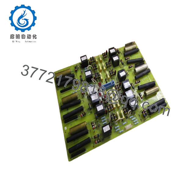
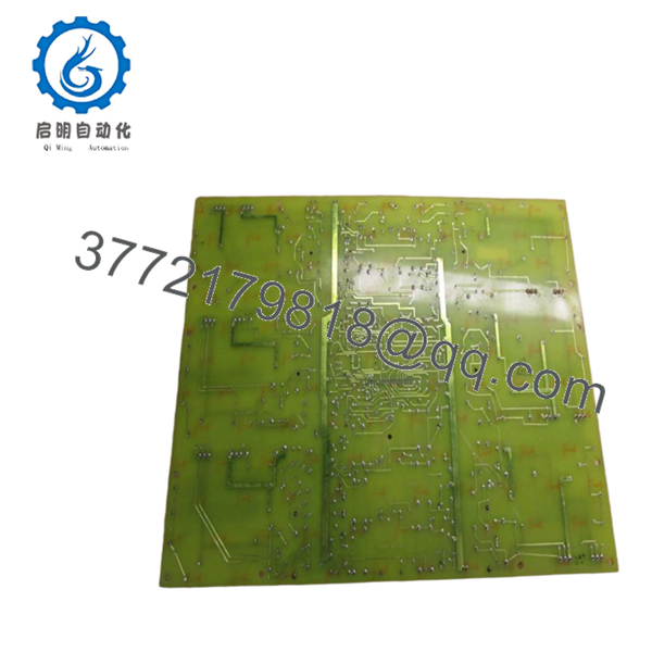
Available technical references identify the DS3800NHVM1E1C as a GE Mark IV high voltage board used in Speedtronic turbine control systems.
4. Product Introduction
The GE DS3800NHVM1E1C is a high voltage control board designed for GE Speedtronic Mark IV turbine control systems. The board operates inside the DS3800 rack architecture and supports high voltage handling, relay control, and signal management functions used in gas and steam turbine applications.
In long-running Mark IV installations, these boards are commonly replaced during outage maintenance when capacitor aging, relay wear, or intermittent communication faults begin appearing. Many plants continue sourcing this board to extend operational life instead of committing immediately to a full Mark VIe migration.

- DS3800NHVM1E1C
- DS3800NHVM1E1C
5. Installation & Configuration Guide
Stage 1: Pre-Installation Preparation (Estimated Time: 10 Minutes)
⚠️ Safety First
- Notify operations and verify the turbine is in a safe shutdown state.
- Lock out and tag out all cabinet power sources.
- Wait at least 5 minutes for capacitor discharge before touching the rack.
Tools Required
- Grounded ESD wrist strap
- PH1 screwdriver
- Fluke 115 multimeter
- Wire labels
- Smartphone for photos
- Flashlight for rack inspection
Data Backup
- Export available control configuration files.
- Photograph:
- Board slot location
- DIP switch settings
- Jumper positions
- Ribbon cable routing
- Record cabinet labels and firmware revisions.
❗ I’ve seen engineers lose half a shift because two visually similar DS3800 boards got swapped during a midnight outage. One rack photo before removal would have prevented it.
Stage 2: Removing the Old Module (Estimated Time: 5 Minutes)
- Remove cabinet covers carefully.
- Label all ribbon cables and wiring.
- Disconnect connectors evenly without flexing the PCB.
- Release retention clips or mounting screws.
- Pull the board straight outward from the rack guides.
- Inspect:
- Backplane pins
- Connector oxidation
- Dust buildup
- Heat discoloration around relays and capacitors
⚠️ Note: Keep the original board nearby until the replacement completes startup testing successfully.
Older Mark IV cabinets often contain undocumented field modifications. Never assume the prints match reality.
Stage 3: Installing the New Module (Estimated Time: 10 Minutes)
- Wear the grounded ESD strap before touching the replacement board.
- Verify exact part number:
- DS3800NHVM1E1C
- Inspect the board for:
- Corrosion
- Rework marks
- Cracked solder joints
- Damaged edge connectors
- Configuration Clone (Crucial):
- Match all jumper settings
- Duplicate DIP switch positions exactly
- Verify any termination settings
- Insert the board carefully into rack guides.
- Press evenly until fully seated into the backplane connector.
- Tighten retention hardware properly.
- Reconnect all ribbon cables and field wiring.
Self-Checklist
- DIP switches match
- Jumpers verified
- Connectors seated fully
- Rack tabs locked
- No loose tools inside cabinet
❗ This is the most common rookie mistake, but experienced maintenance crews still get burned by it during outage pressure. Photograph every jumper before removal.
Stage 4: Power-On & Testing (Estimated Time: 10–15 Minutes)
Pre-Power Check
- Use a multimeter to verify no shorts exist on the 24 V rail.
- Confirm cabinet grounding continuity.
- Verify no tools or loose hardware remain inside the enclosure.
Power-On Steps
- Energize the rack only.
- Observe startup LED behavior.
- Green indicators typically mean successful initialization
- Red fault LEDs indicate startup or communication issues
- Connect the engineering workstation.
- Verify:
- Rack communication
- Board recognition
- System diagnostics
- Reload configuration data if required.
- Perform dry-run I/O testing before enabling field outputs.
⚠️ Troubleshooting Note
- Solid red fault LEDs often indicate firmware or configuration mismatch.
- No communication usually traces back to:
- Bent backplane pins
- Incorrect jumper settings
- Poor connector seating
I’ve personally watched a turbine startup delayed nearly 14 hours because a replacement board shipped with factory-default jumper settings that didn’t match the original cabinet configuration.
6. Frequently Asked Questions (FAQ)
Q1: Can I hot-swap the DS3800NHVM1E1C under power?
No. Do not hot-swap this board.
The Mark IV platform was not designed for online board replacement. Pulling the module live can damage the backplane or create unstable control conditions during turbine operation. Shut the rack down completely first.
Q2: Is the DS3800NHVM1E1C obsolete?
Yes. This board is obsolete from the OEM manufacturing perspective.
Current market availability normally comes from:
- New surplus inventory
- Decommissioned plant stock
- Refurbished and tested boards
Many utilities and industrial plants continue maintaining Mark IV systems because migration projects require significant outage planning and capital budget approval.
Q3: What does this board actually do in the Mark IV system?
The DS3800NHVM1E1C functions as a high voltage interface and control board inside the Speedtronic Mark IV architecture. It contains relay circuits, capacitors, diodes, and voltage-handling components used for turbine control functions.
Exact behavior varies by cabinet configuration and turbine package.
Q4: Will replacing this board erase my control logic?
Usually no, but never assume memory retention in older turbine systems.
Before replacement:
- Back up all available configuration data
- Photograph switch settings
- Record firmware revisions
I’ve seen projects where a newer replacement revision introduced subtle communication timing differences that caused intermittent startup faults for two days.
Q5: What is the biggest installation mistake engineers make with these boards?
❗ Jumper and DIP switch mismatch.
This happens constantly during outage work. Factory-default settings rarely match the original field configuration. Take clear photos before removal and duplicate every setting exactly.
I can’t stress this enough.
Q6: Why are some “new” boards cheaper than expected?
Because most available inventory today comes from surplus channels rather than active OEM production.
Lower pricing can result from:
- Warehouse liquidation
- Plant shutdown inventory
- Open-box surplus stock
That said, always request:
- Actual photos
- Test reports
- Power-up verification
- Serial number documentation
If a seller only uses stock photos, proceed carefully.
Q7: What QC process should a serious supplier perform?
Minimum acceptable testing should include:
- Visual inspection under magnification
- Anti-counterfeit verification
- 500 V insulation resistance testing (>10 MΩ)
- Ground continuity verification
- Rack communication testing
- 24-hour powered burn-in test
- ESD-safe packaging and anti-static sealing
Good suppliers usually test these boards on genuine GE Mark IV racks and provide startup videos or test photos upon request.
Keep these checks in mind and you’ll avoid most replacement-related rework.


