
 WhatsApp: +86 16626708626
 Email:
  Phone: +86 16626708626
Description
3. Key Technical Specifications
Because GE documentation for DS3800NPZA1F1C is limited in the public domain, several values below require verification against site drawings and OEM documentation before installation. The board is identified as a GE power supply board used in legacy Mark IV environments.
| Parameter | Value |
|---|---|
| Manufacturer | GE General Electric |
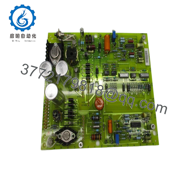
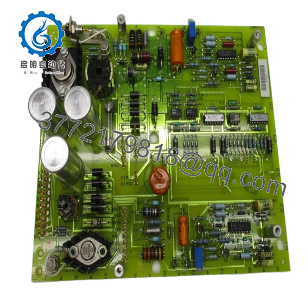
| Model | DS3800NPZA1F1C |
| Product Type | Power Supply Board |
| Series | GE Mark IV Speedtronic |
| Mounting Method | Rack / Cabinet PCB installation |
| Primary Use | Turbine control power regulation |
| System Application | Speedtronic control systems |
| Condition Options | New Surplus / Refurbished |
| Operating Environment | Industrial control cabinets |
| Installation Type | Plug-in board assembly |
| Availability | Limited due to legacy status |
| Warranty | Typically 12 months depending on stock source |
4. Product Introduction
GE DS3800NPZA1F1C is a power supply board used in GE Mark IV Speedtronic turbine control systems. It supports power regulation and internal board-level distribution functions within legacy gas turbine control cabinets. Public documentation identifies it as a replacement component for established GE installations.
In field deployments of older Speedtronic systems, maintaining board revision consistency matters more than price. Engineers typically choose the same suffix revision because small hardware changes across legacy GE boards can create startup problems during commissioning.

- DS3800NPZA1F1C
5. Installation & Configuration Guide
Stage 1: Pre-Installation Preparation (Estimated: 10 minutes)
⚠️ Safety First: Notify operations of downtime. Verify equipment is in a safe state. Apply lockout/tagout. Wait at least 5 minutes for DC bus capacitor discharge.
Tools Required:
- ESD wrist strap
- PH1 screwdriver
- Fluke 115 multimeter
- Wire labels
- Smartphone for photos
- Flashlight
- ESD work mat
Data Backup:
- Export turbine controller configuration if accessible.
- Record cabinet identifiers and rack slot positions.
- Photograph all wiring.
- Photograph DIP switches and jumper positions.
- Record firmware and hardware revision data.
⚠️ Legacy Mark IV cabinets often contain undocumented field modifications. Assume nothing.
Stage 2: Removing the Old Module (Estimated: 5 minutes)
- Remove front covers and access panels.
- Label every connector before removal.
- Disconnect wiring carefully. Never pull on wires.
- Release rack locking tabs.
- Pull the board straight outward.
- Inspect edge connectors and backplane pins.
⚠️ Keep the old module nearby until startup is complete.
I’ve seen technicians throw failed boards into a box immediately. Two hours later they realized the jumper configuration was undocumented.
Stage 3: Installing the New Module (Estimated: 10 minutes)
- Wear grounded ESD protection.
- Verify DS3800NPZA1F1C part number and suffix exactly match.
- Configuration Clone (Crucial): Duplicate every jumper and DIP setting from the original board.
Pay close attention to:
- Address selection
- Termination settings
- Hardware jumpers
- Revision labels
This is the most common rookie mistake, but it happens constantly. Take a picture before you pull it. I can’t stress this enough.
- Insert board straight into guides.
- Confirm full seating into backplane connectors.
- Tighten retention hardware.
Self-Checklist
- DIPs match
- Wiring secured
- Locking tabs engaged
Stage 4: Power-On & Testing (Estimated: 10 minutes)
Pre-Power Check
Use a multimeter to verify no short exists on the 24 V rail.
Power sequence:
- Energize rack only.
- Observe LED sequence.
- Verify status indicators.
- Connect engineering workstation.
- Confirm communication status.
- Perform dry-run I/O verification.
Green RUN typically indicates healthy startup.
Red ERR requires investigation.
⚠️ Troubleshooting Note: If startup faults appear immediately, suspect revision mismatch before replacing hardware again.
I’ve seen projects lose two days because a newer board revision changed communication behavior between firmware families.
SOP Quality Transparency
Inbound Inspection & Traceability
- Verify OEM labels and shipment records.
- Perform anti-counterfeit inspection.
- Check serial numbers and holograms.
- Inspect for scratches, corrosion, rework marks, and UV yellowing.
- Verify manuals and certificates.
Live Functional Testing
Testing performed using an authentic GE-compatible rack or simulation environment where available.
Steps:
- Power-on self-test
- LED verification
- Communication checks
- I/O simulation
- Continuous run testing exceeding 24 hours
- Thermal monitoring
Official test reports generated after completion.
Electrical Testing
- 500 V Megger insulation test: >10 MΩ
- Ground continuity verification
- Hipot testing where applicable
Firmware Verification
- Record firmware revision
- Photograph jumper settings
- Archive configuration data
Final QC
- Inspector signoff
- Anti-static ESD packaging
- Bubble wrap protection
- Heavy-duty corrugated box
- QC date labeling
Test photos and videos available upon request.
Technical Pitfall & Survival Guide
❗ Firmware Revision Mismatch
Document existing firmware before removal.
I saw one installation where a replacement shifted from V2.8 to V3.1. Result: communication timeout alarms for two days.
❗ DIP Switch Errors
Take photos before removal.
This sounds basic. It still causes repeat shutdowns every year.
❗ Terminal Wiring Differences
Even GE revisions can alter connector definitions.
Never wire from memory.
❗ Power Draw Limits
Calculate total cabinet consumption and maintain at least a 20% power margin.
Small additions accumulate quickly.
❗ ESD Damage
Wear grounding protection.
I once watched an engineer handle a board during dry winter weather without a wrist strap. Powered it up and smoke appeared immediately. Thousands of dollars disappeared in ten seconds.
Keep these checks in mind and you’ll save yourself 90% of typical rework time.
6. Frequently Asked Questions (FAQ)
Q1: Can I hot-swap this module?
No. Treat this board as non-hot-swappable.
Removing or inserting boards with power applied can damage the backplane and neighboring modules. Kill power first.
Q2: Is DS3800NPZA1F1C obsolete?
Yes. This belongs to a legacy GE Mark IV family and availability is limited. Most inventory today comes from surplus channels or refurbished stock.
Q3: Is this genuinely new or refurbished?
Depends on inventory source.
New Surplus usually means unused older stock. Refurbished means previously deployed hardware tested and restored. Ask for test reports and photos. Do not accept vague wording.
Q4: Will I lose logic or programming if I replace the board?
Normally no.
Program execution and logic storage usually reside elsewhere in the controller architecture. Still, always back up system configuration before removal.
Q5: What if this exact suffix is unavailable?
Stay with identical hardware revisions whenever possible.
DS3800 series boards can contain undocumented revision changes. Verify compatibility before substituting.
Q6: Why are surplus prices lower than OEM list prices?
Simple reason: inventory age.
Many suppliers purchased spare stock years ago and now distribute remaining inventory. Lower pricing does not automatically mean lower quality. Ask for inspection records and test documentation.
Q7: Do you provide warranty coverage?
Most suppliers provide a one-year warranty on tested units. Read the terms carefully and verify whether coverage includes replacement only or field labor reimbursement.


