
 WhatsApp: +86 16626708626
 Email:
  Phone: +86 16626708626
Description
3. Key Technical Specifications
| Parameter | Value |
|---|---|
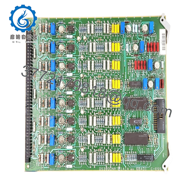
| Model Number | DS3800NRTB1A1A |
| Manufacturer | General Electric |
| Product Category | RTD Conditioning Board |
| System Platform | Speedtronic Mark IV DS3800 |
| Primary Function | RTD signal conditioning |
| Application | Gas and steam turbine control |
| Communication Method | Dual PCB mating connectors |
| Female Connector | AMP 218A4551-1 / 102041-1 |
| Secondary Connector | Right-angle 13-pin male connector |
| Handling Features | Factory-installed extractor clips |
| Board Construction | Carbon composite and metal film resistors |
| Capacitor Types | Polyester vinyl and aluminum electrolytic |
| Product Lifecycle | Obsolete |
| Available Conditions | New Surplus / Refurbished (tested) |
The board uses two mating connectors and includes extractor clips intended to reduce direct handling of sensitive circuitry during installation and removal.
4. Product Introduction
GE DS3800NRTB1A1A is an RTD conditioning board used in the GE Speedtronic Mark IV turbine control architecture. Its job is to process and condition resistance temperature detector (RTD) signals before they are transferred into the control environment for monitoring and protection functions.
In field deployments of Mark IV systems, temperature input cards matter more than many people realize. A drifting RTD board can create false temperature values and trigger nuisance alarms or fuel control issues. Plants maintaining long-life turbine assets often keep spare boards because unplanned failures can create extended outage windows.
- DS3800NRTB1A1A
- DS3800NRTB1A1A
5. Installation & Configuration Guide
Stage 1: Pre-Installation Preparation (Estimated: 10 minutes)
⚠️ Safety First: Notify operations before shutdown. Confirm turbine equipment is in a safe state. Lock out and tag out control power. Wait 5 minutes minimum for capacitor discharge.
Tools Required:
- ESD wrist strap
- PH1 screwdriver
- Fluke 115 multimeter
- Wire labels
- Smartphone camera
- ESD mat
Data Backup
- Export control configuration if available.
- Record cabinet status and alarm conditions.
- Photograph connector orientation.
- Photograph field wiring positions.
- Document board revision labels.
I’ve walked into outage jobs where someone skipped photographs because they thought connector locations were obvious. Thirty minutes later they were tracing cables with a flashlight.
Stage 2: Removing the Old Module (Estimated: 5 minutes)
- Remove cabinet access panels.
- Label and disconnect all wiring.
- Release retention hardware.
- Use extractor clips and remove board straight outward.
- Inspect connector pins and backplane interfaces.
⚠️ Do not twist the board during removal.
These old Mark IV connectors do not tolerate abuse well.
⚠️ Keep the old module nearby until startup succeeds.
Stage 3: Installing the New Module (Estimated: 10 minutes)
- Attach ESD protection before touching circuitry.
- Verify exact part number: DS3800NRTB1A1A
- Configuration Clone (Crucial): Match connector orientation and any jumper settings.
- Insert board carefully until fully seated.
- Secure retention hardware.
- Reconnect wiring.
Self-Checklist:
- Correct board revision
- Wiring secured
- Connectors seated
- Retention hardware locked
- ESD procedures followed
⚠️ This is the most common rookie mistake, but it happens constantly. Take a picture before you pull it. I can’t stress this enough.
Stage 4: Power-On & Testing (Estimated: 10 minutes)
Pre-Power Check
Verify no shorts across the 24 V DC rail with a Fluke meter.
Power-On procedure:
- Power the control rack first.
- Observe indicators and diagnostics.
- Verify communication status.
- Review RTD input values.
- Simulate temperature signals if possible.
⚠️ Troubleshooting Note: Unexpected RTD values often indicate wiring polarity mistakes or board revision differences before actual hardware failure.
Technical Pitfall & Survival Guide
❗ Firmware Revision Mismatch
Issue: Revision changes occasionally affect interaction with older hardware.
Avoidance: Record every board revision before replacement.
I’ve seen maintenance crews chase a communication alarm for two days after swapping in a newer revision board.
❗ DIP Switch / Jumper Misconfiguration
Issue: Site settings rarely match default configurations.
Avoidance: Photograph everything before removal.
Night-shift replacements create most of these problems.
❗ Terminal Block / Wiring Incompatibility
Issue: Connector arrangements occasionally differ by suffix revision.
Avoidance: Compare physical layouts before installation.
Even similar GE boards can route signals differently.
❗ Power Draw Specifications
Issue: Existing supplies may already operate near limits.
Avoidance: Maintain approximately 20% power reserve margin.
Legacy cabinets usually have less spare capacity than maintenance teams assume.
❗ Electrostatic Discharge (ESD)
Issue: Static damage can happen before installation.
Avoidance: Use grounded straps and ESD work surfaces.
I watched a board get unpacked during winter with no strap protection. Smoke came immediately after power-up. Expensive lesson.
Keep these checks in mind and you’ll save yourself 90% of typical rework time.
6. Frequently Asked Questions (FAQ)
Q1: Can I hot-swap this module?
No.
Mark IV hardware predates modern hot-swap architectures. Removing or inserting boards under power can damage connectors or create backplane faults.
Q2: Is GE DS3800NRTB1A1A obsolete?
Yes.
The Speedtronic Mark IV family is a legacy GE platform. Current inventory generally comes from surplus stock or refurbishment channels.
Q3: Is this board genuinely new?
Usually “New Original” means unused surplus inventory stored in industrial stockrooms.
Factory packaging may not always survive decades of storage. Request photos and serial information.
Q4: What is the direct replacement if inventory becomes unavailable?
There is not always a straightforward cross-reference.
GE Mark IV hardware often depends on exact suffix versions. Verify with system documentation before substituting variants.
Q5: Will I lose programming when replacing this board?
No, not typically.
This board conditions RTD inputs and does not store primary turbine logic. Still, always perform a system backup before maintenance work.
Q6: Why are some surplus prices lower than historical OEM prices?
Because OEM production stopped years ago.
Pricing now depends on condition, test history, and available inventory. New-surplus stock and tested refurbished boards can vary substantially.
Q7: How are boards tested before shipment?
Our SOP follows a documented engineering process:
- Source traceability and serial verification
- Counterfeit inspection and visual checks
- Inspection for UV yellowing, corrosion, or repair marks
- Functional testing on genuine GE-compatible hardware where available
- Communication verification
- 500 V Megger insulation test (>10 MΩ)
- Firmware and revision documentation
- QC sign-off and ESD packaging
Test photos and videos are available upon request.
Hardware details and connector specifications are based on documented DS3800NRTB1A1A field information.


