
 WhatsApp: +86 16626708626
 Email:
  Phone: +86 16626708626
Description
3. Key Technical Specifications
| Parameter | Value |
|---|---|
| Manufacturer | GE General Electric |
| Model Number | DS3800NTBD |
| Product Series | Speedtronic Mark IV |
| Functional Description | Analog Termination Board |
| Product Type | PCB Termination Module |
| Application | Gas and steam turbine control systems |
| Primary Function | Field signal termination for DS3820STMA |
| Mounting Method | DIN rail / screw-mounted |
| Connector Configuration | 1 × 37-pin female, 2 × male PCB connectors |
| Jumper Configuration | 12 configurable jumper switches |
| Board Markings | NTBD 6DA05 / NTBD 6FA05 |
| Power Source | Backplane-connected |
| System Compatibility | GE Mark IV Speedtronic |
| Operating Environment | Industrial control cabinet |
| Firmware Dependency | Verify compatibility with installed Mark IV revision |
| Availability | Limited surplus inventory |
| Typical Lead Time | 3–7 business days depending on stock |
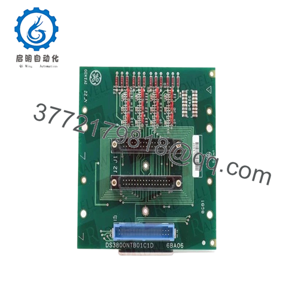
The DS3800NTBD is identified as a termination module used with the larger DS3820STMA card inside GE Mark IV turbine control systems. The board provides analog field wiring termination and includes multiple configurable jumpers and PCB mating connectors for signal routing.
4. Product Introduction
The GE DS3800NTBD is an analog termination PCB used in GE Speedtronic Mark IV gas and steam turbine control systems. It serves as the field wiring interface for associated I/O hardware, particularly the DS3820STMA assembly, and mounts directly within the Mark IV cabinet infrastructure.
In operating turbine plants, boards like the DS3800NTBD are commonly retained as strategic spare inventory because replacing a failed termination board is significantly faster than redesigning cabinet wiring or migrating to a newer control platform. The board’s jumper-configurable architecture also allows adaptation to site-specific analog signal configurations.
- DS3800NTBD
5. Installation & Configuration Guide
Stage 1: Pre-Installation Preparation (Estimated Time: 10 Minutes)
⚠️ Safety First
- Notify operations and maintenance personnel of the outage.
- Verify the turbine is fully shut down and in a safe state.
- Apply lock out/tag out (LOTO) procedures.
- Wait at least 5 minutes for cabinet capacitors to discharge.
Tools Required
- ESD wrist strap
- PH1 screwdriver
- Fluke 115 multimeter or equivalent
- Wire labels
- Smartphone for reference photos
- Flashlight for cabinet inspection
Data Backup
- Record cabinet slot location and associated field wiring.
- Photograph all jumper switch settings before removal.
- Label field wiring carefully.
- Document any cabinet alarm conditions before shutdown.
❗ This is where experienced techs save themselves hours later. I’ve watched people remove termination boards without labeling wires because “it’s only a few terminals.” Four hours later they’re tracing analog loops one wire at a time.
Stage 2: Removing the Old Module (Estimated Time: 5–10 Minutes)
- Open cabinet access panels carefully.
- Identify the DS3800NTBD termination board.
- Label and disconnect field wiring methodically.
- Remove DIN rail retention hardware if installed.
- Pull the board straight out without twisting the connectors.
- Inspect connectors and terminals for:
- Corrosion
- Bent pins
- Heat discoloration
- Loose terminal screws
⚠️ Important Note
Keep the original board nearby during commissioning. Even failed boards provide critical reference information for jumper positions and wiring orientation.
Stage 3: Installing the New Module (Estimated Time: 10 Minutes)
Installation Steps
- Wear grounded ESD protection before handling the PCB.
- Verify the replacement part number exactly matches:
- DS3800NTBD
- Compare all connector layouts and jumper positions with the removed board.
- Configuration Clone (Crucial):
- Replicate all jumper switch settings exactly.
- Pay attention to:
- RST jumpers
- ADB2 settings
- ADB5 settings
- PAR jumper configuration
- Mount the board securely onto the DIN rail or cabinet hardware.
- Reconnect field wiring using proper terminal torque.
- Verify all connectors are fully seated.
Self-Checklist
- Model verified
- Jumper settings copied
- Wiring labeled correctly
- Connectors seated fully
- Mounting secured
❗ Jumper mistakes are constant on these older GE boards. A single misplaced jumper can create intermittent analog signal faults that look like bad transmitters or failed AI cards.
Stage 4: Power-On & Testing (Estimated Time: 10–15 Minutes)
Pre-Power Check
- Verify no short exists on cabinet power rails.
- Confirm analog commons and shield grounds are correct.
- Inspect cabinet for loose tools or dropped hardware.
Power-On Steps
- Energize the control rack first.
- Observe cabinet startup diagnostics.
- Verify communication between the termination board and associated I/O assembly.
- Check analog signal values through the HMI or engineering workstation.
- Perform dry-run signal simulation if available.
⚠️ Troubleshooting Note
If analog channels show unstable readings immediately after replacement:
- Recheck jumper settings
- Verify shield grounding
- Inspect connector seating
- Confirm field wiring polarity
- Verify proper DS3820STMA compatibility
I’ve seen entire turbine trips blamed on “bad transmitters” when the actual issue was one incorrect jumper on a termination board after maintenance.
Quality Control & Testing Procedure
1. Inbound Inspection & Traceability
Each DS3800NTBD board undergoes:
- OEM identification verification
- Serial and revision inspection
- Anti-counterfeit visual inspection
- Inspection for corrosion, repaired traces, UV yellowing, and solder damage
- Connector pin integrity verification
2. Live Functional Testing
Testing is performed using GE Mark IV-compatible hardware whenever available.
Procedures include:
- Power-on verification
- Connector continuity testing
- Jumper configuration validation
- Signal path verification
- Continuous energized runtime testing exceeding 24 hours with thermal observation
Test videos and startup photos are available upon request.
3. Electrical Parameter Testing
- 500 V insulation resistance test (>10 MΩ target)
- Ground continuity verification
- Connector continuity checks
- Power rail verification using calibrated Fluke instruments
4. Firmware & Configuration Verification
- Board revision documentation
- Jumper configuration photography
- Connector compatibility inspection
5. Final QC & Packaging
- QC technician approval and sign-off
- Anti-static ESD packaging
- Bubble wrap protection
- Heavy-duty export carton packaging
- QC Passed labeling with inspection date
6. Frequently Asked Questions (FAQ)
Q1: Can the DS3800NTBD be hot-swapped while the Mark IV cabinet is powered?
No.
This board interfaces directly with analog termination circuitry and associated I/O hardware. Pulling it live can destabilize analog inputs or damage the backplane interface.
Shut the cabinet down completely before replacement.
Q2: What exactly does the DS3800NTBD do?
The DS3800NTBD functions as an analog termination board for the GE Mark IV system. It provides field wiring termination and signal routing between plant instrumentation and the associated DS3820STMA assembly.
Q3: Is the DS3800NTBD obsolete?
Yes.
The DS3800NTBD belongs to the legacy GE Speedtronic Mark IV platform, which has been out of OEM production for many years. Most current inventory comes from surplus stock or tested refurbishment channels.
That is why lead times and pricing fluctuate heavily.
Q4: Why are jumper settings so important on this board?
Because the jumpers determine signal routing and board behavior.
The DS3800NTBD contains twelve configurable jumpers grouped for multiple configuration functions. One wrong setting can cause incorrect analog scaling, signal instability, or communication faults.
❗ Take photos before removal. I can’t stress this enough.
Q5: Will replacing this board erase turbine control logic?
Normally no.
This board primarily handles termination and signal routing. The turbine logic itself resides elsewhere in the Mark IV control architecture. Still, always back up configuration data and document all hardware settings before maintenance.
Q6: What is the most common installation mistake?
Incorrect jumper replication and wiring reversal.
I’ve seen technicians reconnect analog pairs backwards after rushing through a shutdown window. The control room suddenly sees impossible process values and everyone starts suspecting transmitters or AI modules.
Slow down and verify every terminal.
Q7: Why are some surplus GE Mark IV boards much cheaper than others?
Usually because of condition differences.
Pricing depends on:
- Tested versus untested inventory
- Cosmetic condition
- Traceability documentation
- Connector condition
- Whether live rack testing was performed
If a seller cannot provide actual board photos, inspection records, or testing details, proceed carefully.
Keep these checks in mind and you’ll avoid most of the painful troubleshooting sessions that happen during legacy Mark IV maintenance outages.


