
 WhatsApp: +86 16626708626
 Email:
  Phone: +86 16626708626
Description
3. Key Technical Specifications
| Parameter | Value |
|---|---|
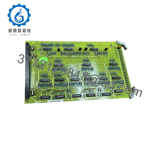
| Part Number | DS3815CCMB |
| Manufacturer | General Electric |
| Product Type | Communication Control Board |
| Functional Description | CCM2 Protocol Control Module |
| Series | Speedtronic Mark IV DS3815 |
| System Compatibility | GE Mark IV turbine control systems |
| Installation Method | Rack-mounted PCB |
| Communication Function | CCM2 protocol handling |
| Connector Type | Edge backplane connectors |
| Mounting Style | Retention screw secured |
| Application | Gas and steam turbine control systems |
| Cooling Method | Passive cabinet airflow |
| Operating Environment | Industrial turbine control cabinet |
| Condition Options | New Surplus / Refurbished Tested |
| Availability | Limited surplus inventory globally |
Market references identify the DS3815CCMB as a GE CCM2 protocol control module associated with Mark IV turbine control architectures.
4. Product Introduction
The GE DS3815CCMB is a communication and protocol handling board used in GE Speedtronic Mark IV turbine control systems. The module operates within the DS3815 hardware family and supports CCM2 protocol-related control and communication functions inside turbine control cabinets.
In field maintenance environments, these boards are typically sourced for lifecycle extension projects where plants continue operating legacy Mark IV systems rather than scheduling a complete controls migration. Engineers usually replace these boards after intermittent communication faults, aging component failures, or protocol instability during turbine startup sequences.

- DS3815CCMB
- DS3815CCMB
5. Installation & Configuration Guide
Stage 1: Pre-Installation Preparation (Estimated Time: 10 Minutes)
⚠️ Safety First
- Notify operations and place the turbine in a verified safe shutdown state.
- Lock out and tag out all cabinet power sources.
- Wait at least 5 minutes for capacitor discharge before opening the rack.
Tools Required
- Grounded ESD wrist strap
- PH1 screwdriver
- Fluke 115 multimeter
- Wire labels
- Smartphone for cabinet photos
- Flashlight for connector inspection
Data Backup
- Export available Mark IV configuration files.
- Photograph:
- Rack slot location
- Ribbon cable routing
- Jumper positions
- DIP switch settings
- Record all board revision labels and maintenance markings.
❗ I’ve watched experienced techs lose an entire shift because two nearly identical DS3815 boards got swapped during a night outage. One photo before removal would have prevented it.
Stage 2: Removing the Old Module (Estimated Time: 5 Minutes)
- Remove cabinet access covers carefully.
- Label all connectors and ribbon cables.
- Disconnect wiring evenly without twisting the PCB.
- Release retention hardware or rack tabs.
- Pull the board straight outward from the rack guides.
- Inspect:
- Backplane pins
- Connector oxidation
- Dust accumulation
- Heat discoloration around communication components
⚠️ Note: Keep the original board available until the replacement completes startup testing successfully.
Older Mark IV systems often contain undocumented field modifications that never made it into the prints.
Stage 3: Installing the New Module (Estimated Time: 10 Minutes)
- Wear the grounded ESD strap before handling the board.
- Verify exact model number:
- DS3815CCMB
- Inspect the replacement PCB for:
- Rework marks
- Corrosion
- Cracked solder joints
- Damaged edge connectors
- Configuration Clone (Crucial):
- Match all DIP switches exactly
- Duplicate jumper settings from photos
- Verify communication addressing configuration
- Insert the board carefully into rack guides.
- Press evenly until fully seated into the backplane connector.
- Tighten mounting hardware securely.
- Reconnect all wiring and ribbon cables.
Self-Checklist
- DIP switches match
- Jumpers verified
- Connectors fully seated
- Rack tabs locked
- No loose hardware inside cabinet
❗ This is the most common rookie mistake, but it still catches veteran maintenance crews during outage pressure. Photograph every jumper before removal.
Stage 4: Power-On & Testing (Estimated Time: 10–15 Minutes)
Pre-Power Check
- Use a multimeter to verify no shorts exist on the 24 V rail.
- Confirm cabinet grounding continuity.
- Verify no tools remain inside the enclosure.
Power-On Steps
- Energize the control rack only.
- Observe startup LED activity.
- Verify communication initialization.
- Connect the engineering workstation.
- Confirm:
- Rack communication
- Protocol handshake
- Diagnostic status
- Reload configuration data if required.
- Perform dry-run communication testing before enabling field devices.
⚠️ Troubleshooting Note
- Solid fault LEDs commonly indicate firmware or addressing mismatch.
- No communication usually traces back to:
- Incorrect DIP switch settings
- Bent backplane pins
- Connector seating problems
I’ve personally seen a Mark IV startup delayed almost 16 hours because a replacement communication board shipped with different factory-default addressing than the original site hardware.
6. Frequently Asked Questions (FAQ)
Q1: Can I hot-swap the DS3815CCMB while the rack is powered?
No. Do not hot-swap this module.
The GE Mark IV architecture was not designed for live board insertion. Pulling or inserting the board under power can damage the backplane or corrupt communication traffic across the control rack.
Q2: Is the DS3815CCMB obsolete?
Yes. This module is obsolete from the OEM manufacturing standpoint.
Current inventory generally comes from:
- New surplus stock
- Plant spare inventory
- Refurbished tested boards
Many utilities continue operating Mark IV systems because migration projects require major outage coordination and capital approval.
Q3: What does “CCM2 Protocol” actually mean here?
The board handles communication and protocol management functions within the Mark IV control architecture. Exact implementation varies depending on turbine package configuration and cabinet revision.
Always verify against original GE prints and site documentation before replacement.
Q4: Will replacing this board erase turbine logic or configuration?
Usually no, but never assume memory retention in older turbine systems.
Before removal:
- Back up configuration files
- Record firmware versions
- Photograph jumper settings
I’ve seen projects where a newer board revision introduced subtle communication timing differences that caused intermittent startup faults for two days.
Q5: What is the biggest installation mistake with these modules?
❗ DIP switch and jumper mismatch.
This happens constantly during outage work. Factory-default settings almost never match the original field configuration. Take clear photos before removal and duplicate every setting exactly.
I can’t stress this enough.
Q6: Why are surplus prices lower than historical OEM pricing?
Because GE no longer manufactures these modules through normal production channels.
Pricing now depends on:
- Remaining global inventory
- Plant shutdown recoveries
- Refurbishment availability
- Demand from active Mark IV operators
Used market pricing for DS3815CCMB boards has recently appeared in the USD 5,000–6,000 range depending on condition and warranty coverage.
Q7: What testing should a supplier perform before shipment?
Minimum acceptable testing should include:
- Visual inspection under magnification
- Anti-counterfeit verification
- 500 V insulation resistance testing (>10 MΩ)
- Ground continuity verification
- Rack communication testing
- 24-hour powered burn-in test
- ESD-safe packaging and anti-static sealing
Good suppliers usually test these modules on genuine GE Mark IV racks and provide startup videos or test photos upon request.
Keep these checks in mind and you’ll avoid most replacement-related rework.


