
 WhatsApp: +86 16626708626
 Email:
  Phone: +86 16626708626
Description
3. Key Technical Specifications
| Parameter | Value |
|---|---|
| Model Number | F650NFLF2G5HIP6E |
| Manufacturer | GE Multilin (GE Grid Solutions / GE Vernova) |
| Product Type | Numerical Feeder Protection Relay |
| Rated Frequency | 50/60 Hz ±10% |
| Current Inputs | 1 A or 5 A (configuration dependent) |
| Voltage Supply | 120/240 V AC/DC (configuration dependent) |
| Protection Functions | 50/51, 50N/51N, 67/67N, 27/59, 81, 50BF, 79, Thermal Protection |
| Communications | IEC 61850 Ed.2, Modbus RTU/TCP, DNP3, IEC 60870-5-103/104 |
| Ethernet Ports | Dual Ethernet (configuration dependent) |
| Display | Graphical LCD with local keypad |
| Event Recording | Oscillography, fault records, event logs |
| Typical Applications | Utility substations, industrial feeders, renewable energy distribution, SCADA integration |
4. Product Introduction
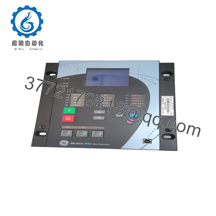
The GE F650NFLF2G5HIP6E is a member of the Multilin F650 feeder protection relay family designed for medium- and high-voltage feeder protection, automation, and bay control. It combines protection, metering, monitoring, breaker control, disturbance recording, and communications in a single intelligent electronic device (IED).
The relay is widely deployed in utility substations, industrial power distribution systems, renewable energy facilities, and large manufacturing plants. Its support for IEC 61850, DNP3, and Modbus allows straightforward integration into modern SCADA and substation automation systems while maintaining compatibility with existing infrastructure.

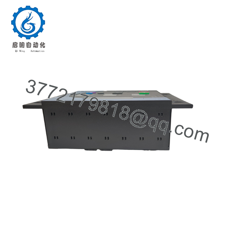
- F650NFLF2G5HIP6E
- F650NFLF2G5HIP6E
5. Installation & Configuration Guide
Stage 1 – Pre-Installation Preparation (10–15 minutes)
⚠️ Safety First
- Notify plant operations before taking the feeder out of service.
- Open and isolate all associated breakers.
- Apply Lock-Out/Tag-Out (LOTO) procedures.
- Verify all CT and VT circuits are de-energized where applicable.
- Wear appropriate PPE and use an ESD wrist strap.
Tools Required
- ESD wrist strap
- PH1 screwdriver
- Digital multimeter (Fluke 115 or equivalent)
- Insulation tester (if required)
- Laptop with EnerVista UR Setup / F650 Setup software
- Smartphone for recording wiring
Data Backup
- Save the complete relay settings file.
- Export logic equations and setting groups.
- Record firmware version.
- Photograph every terminal block before removal.
- Record Ethernet and serial communication settings.
Stage 2 – Removing the Existing Relay (10 minutes)
- Open the relay panel.
- Label every CT, VT, digital I/O, and communication cable.
- Disconnect communication cables first.
- Remove terminal blocks carefully.
- Unscrew the mounting hardware.
- Remove the relay without stressing rear connectors.
⚠️ Do not discard the original relay until all protection testing has been completed.
Stage 3 – Installing the Replacement Relay (15 minutes)
- Verify the complete ordering code F650NFLF2G5HIP6E.
- Confirm the current input rating (1 A or 5 A) matches the existing installation.
- Install the relay into the panel cutout.
- Reconnect every terminal according to the recorded wiring.
- Restore Ethernet, RS485, or fiber connections.
- Upload the saved settings using EnerVista.
Self-Checklist
- ✔ Model number verified
- ✔ CT polarity correct
- ✔ VT wiring verified
- ✔ Communications restored
- ✔ Settings successfully loaded
Stage 4 – Power-On & Functional Testing (20–30 minutes)
Pre-Power Checks
- Verify auxiliary power voltage.
- Check CT secondary circuits are never left open.
- Confirm grounding continuity.
Startup Procedure
- Apply auxiliary power.
- Verify successful relay startup.
- Check self-diagnostics.
- Confirm communication with SCADA.
- Verify breaker status indications.
- Inject secondary current and voltage for protection testing.
- Confirm event recording and trip outputs.
⚠️ Troubleshooting
- Relay remains in self-test: Verify auxiliary supply voltage.
- SCADA communication failure: Check IP address, subnet mask, and protocol configuration.
- Protection pickup incorrect: Verify CT ratio and VT scaling.
- Breaker trip failure: Inspect output relay wiring and trip circuit supervision.
6. Frequently Asked Questions (FAQ)
Q1. Can I replace this relay without changing the protection settings?
Usually yes, provided the replacement has the same hardware configuration and firmware compatibility. Always upload the original settings file and verify every protection element before energizing the feeder.
Q2. Does the F650 support IEC 61850?
Yes. The F650 supports IEC 61850 Edition 2 along with DNP3, Modbus RTU/TCP, and IEC 60870-5-103/104, making it suitable for modern substation automation systems.
Q3. Can this relay be used for both utility and industrial feeders?
Yes. It is designed for distribution feeders in utility substations as well as industrial plants, renewable energy installations, and commercial power systems requiring comprehensive feeder protection and control.
Q4. Is the F650NFLF2G5HIP6E still available?
This is a legacy configuration. New Original (New Surplus) units are available from surplus inventory in limited quantities, while professionally tested refurbished units remain common in the industrial spare parts market.
Q5. Will replacing the relay erase fault records?
Yes. Fault records stored in the original relay are not automatically transferred. Before removing the relay, download oscillography, event logs, and disturbance records if they may be needed for maintenance or incident analysis.
Q6. Why should I verify the CT ratio before commissioning?
Incorrect CT ratios are one of the most common commissioning mistakes. A mismatched ratio can cause inaccurate metering, nuisance trips, or failure to operate during genuine faults. Always compare relay settings with the installed CT nameplate before energizing the feeder.
Q7. What should be verified before placing the feeder back into service?
A commissioning engineer should confirm:
- Correct hardware configuration
- Firmware compatibility
- CT and VT ratios
- Protection settings loaded successfully
- Communication with SCADA and HMI
- Breaker control operation
- Protection element pickup values
- Successful secondary injection testing
- Event recording and disturbance recorder functionality
Completing these checks before energizing the feeder minimizes commissioning delays and helps ensure the protection scheme operates exactly as designed.



