
 WhatsApp: +86 16626708626
 Email:
  Phone: +86 16626708626
Description
3. Key Technical Specifications
| Parameter | Specification |
| Manufacturer | GE Fanuc / Emerson Automation Solutions |
| Part Number | IC200ALG260 |
| Product Line | VersaMax I/O / PLC System Platform |
| Number of Channels | 8 single-ended input channels |
| Input Signal Ranges | Current: 4 to 20 mA, 0 to 20 mA | Voltage: 0 to 10 Vdc, ±10 Vdc, 1 to 5 Vdc, 0 to 5 Vdc |
| Converter Resolution | 12-bit binary converter layout |
| Update Rate Time | 12 ms maximum for all 8 channels |
| Internal Power Consumption | 20 mA maximum @ 5 Vdc backplane logic rail |
| External Power Requirement | 24 Vdc nominal loop supply (19.2 to 30 Vdc range), 50 mA maximum consumption |
| Input Impedance | Current mode: 250 ohms | Voltage mode: 400k ohms |
| Isolation Barrier | 250 Vac continuous / 1,500 Vac for 1 minute (field-to-logic) |
| Diagnostics Indicators | 1x INT LED (Green = Normal internal module power status) |
4. Product Introduction & Supply Chain Strategy
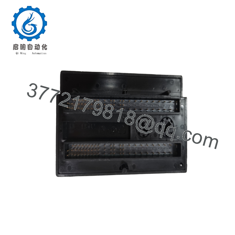
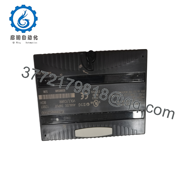
The GE VersaMax IC200ALG260 is an 8-channel, 12-bit analog input module designed to interface directly with VersaMax PLC systems and remote network interface units (NIUs). This high-density module accepts up to eight single-ended analog field signals, including 4–20 mA current loops and 0–10 Vdc voltage spans. It operates as the primary sensing gateway for processing automated telemetry from pressure transmitters, flow meters, temperature transducers, and chemical level sensors.
From an inventory asset management perspective, the IC200ALG260 is an essential component for avoiding long factory wait times and production line downtime. Choosing a New Surplus module avoids the high Total Cost of Ownership (TCO) linked to refurbished hardware. Used analog cards frequently develop subtle tracking errors due to degraded input filters and worn internal analog-to-digital converters (ADCs), which introduce signal drift or channel-to-channel crosstalk. These measurement errors can lead to inaccurate process tracking and unexpected system shutdowns. This factory-sealed New Surplus module delivers true OEM-level accuracy and robust electrical isolation right out of the box.
5. Installation & Configuration Guide
Stage 1: Pre-Installation (Prep & Safety)
- System De-energization: Power down the main VersaMax rack power supply assembly. Isolate and tag out all external 24 Vdc auxiliary loop supplies. Use a digital multimeter to verify that all field terminals register 0 V.
- Terminal Base Verification: Inspect the corresponding IC200CHSxxx terminal carrier base. Ensure the mechanical keying dial is correctly matched for an analog input module to prevent damage during insertion.
- ESD Mitigation: Wear a grounded ESD wrist strap before removing the module from its anti-static shielding to protect the sensitive internal 12-bit converter circuitry.
Stage 2: Removal
- Latch Release: Press the flexible release tabs located on the top and bottom flanges of the module housing.
- Module Extraction: Pull the module straight out, sliding it away from the terminal carrier base. Avoid twisting the module to prevent bending the internal backplane connector pins.
- Base Inspection: Check the terminal carrier base alignment for any physical dust accumulation or loose wire fragments before installing the new unit.
Stage 3: Installation (Clone & Seat)
- Module Alignment: Align the module housing guide pins with the matching channels on the pre-wired terminal carrier base.
- Seating the Module: Push the IC200ALG260 firmly onto the carrier base until the top and bottom plastic clips click into place, securing the module to the rack structure.
- Software Matching: Open your configuration file in Proficy Machine Edition. Verify that the input signal type (such as 4–20 mA current vs. 0–10 V voltage) is configured correctly for each channel slot.
Stage 4: Power-On & Testing
- Power Application: Energize the external 24 Vdc auxiliary loop power supply, then turn on the primary rack backplane power supply.
- LED Status Check: Confirm that the green “INT” LED on the module faceplate lights up solid, indicating healthy internal logic status.
- Signal Calibration Audit: Use a process loop calibrator to inject a known signal (e.g., 12.0 mA) into channel 1. Check your PLC software registers to verify that the analog value scales accurately to the expected digital count.

- IC200ALG260
- IC200ALG260
6. Firmware/Software Versions & Upgrade Notes
The IC200ALG260 relies on fixed, hardware-defined analog signal processing circuitry and a built-in microcontroller microcode stack rather than an updateable flash memory layout. Hardware tracking is managed entirely by the physical board assembly revision level (e.g., IC200ALG260-CA, -DA, or newer).
When replacing an older revision card with a newer New Surplus module within legacy VersaMax networks, ensure your CPU or Network Interface Unit (such as the Profibus IC200BEM003) is running a firmware version that recognizes the module’s hardware profile. Combining early CPU modules (firmware v1.20 or lower) with newer analog revisions can occasionally result in configuration mismatch codes on startup. If this occurs, adjust your software module configuration parameters to use the generic analog input profile baseline.
7. Frequently Asked Questions (FAQ)
- Why should I choose a New Surplus IC200ALG260 rather than a refurbished one? Refurbished analog cards are typically cleaned externally, but their internal optocouplers, input resistors, and power conversion components have already run for thousands of hours under thermal load. This operational wear can lead to calibration drift, which can cause pressure gauges or flow metrics to misread. A New Surplus card provides zero operational hours, factory-certified calibration precision, and original 1,500 Vac field isolation boundaries.
- Can I mix both current loops and voltage inputs on the same module? Yes. The IC200ALG260 allows you to configure individual channels independently through your PLC setup software (such as Proficy Machine Edition). You can assign some channels to read 4–20 mA current loops while setting others to monitor 0–10 Vdc voltage signals, as long as all inputs use single-ended wiring layouts.
- Does this module require external power, or does it run entirely off the PLC backplane? The module requires two separate power feeds. The internal logic gates and communication bus draw 20 mA from the 5 Vdc PLC backplane rail. However, processing the analog loops requires an external 24 Vdc auxiliary power source connected directly to the terminal carrier terminals, consuming up to 50 mA.
- Is it safe to hot-swap this module while the VersaMax rack is powered up? Yes, the VersaMax hardware design supports hot-swapping I/O modules while the backplane is active, provided the terminal carrier base remains securely mounted. However, removing an analog input module during production will instantly drop all eight telemetry loops to zero, which can cause immediate trip faults in your active PLC control logic.
- What is the function of the “INT” LED indicator on the front panel? The “INT” (Internal) LED displays the power and diagnostic status of the module’s onboard logic. A solid green light indicates that the module has successfully completed its power-on self-test and is receiving correct 5 Vdc logic power from the backplane. If the LED remains unlit, it indicates a lack of backplane power or an internal component failure.



