
 WhatsApp: +86 16626708626
 Email:
  Phone: +86 16626708626
Description
3. Key Technical Specifications
| Parameter | Value |
|---|---|
| Number of Channels | 15 single-ended (one group) |
| Input Signal Ranges | 4–20 mA (default) or 0–20 mA (jumper selectable) |
| Resolution | 15 bits |
| Analog Resolution | 0.5 µA = 1 count (4–20 mA); 0.625 µA = 1 count (0–20 mA) |
| Update Rate | 7.5 ms maximum |
| Accuracy (25 °C) | ±0.3 % typical, ±0.5 % maximum of full scale |
| Accuracy (0–60 °C) | ±1 % maximum of full scale |
| Input Impedance | 100 Ω |
| Filter Response | 24 Hz ±20 % (3 dB) |
| Isolation | 250 VAC continuous; 1500 VAC for 1 minute |
| Backplane Current | 100 mA maximum @ 5 VDC |
| External Power Required | None (module power from backplane) |
| Diagnostics | OK LED; loss of internal power; open-wire detection (4–20 mA) |
| Operating Temperature | 0 to 60 °C |
4. Product Introduction
The IC200ALG264H is a 15-channel, 15-bit analog current input module for the GE Fanuc / Emerson VersaMax I/O system. It accepts 4–20 mA or 0–20 mA signals (selected by a carrier jumper) on 15 single-ended channels that share a common return.
The module is powered entirely from the VersaMax backplane (no external power supply required for the module itself). It provides 15-bit conversion resolution, a maximum update rate of 7.5 ms, and basic diagnostics including an OK LED and open-wire detection in 4–20 mA mode. Field transmitter power must be supplied externally. Revision H is a later manufacturing revision with no functional changes from earlier versions.
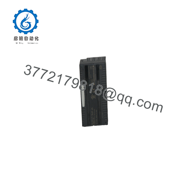
IC200ALG264H
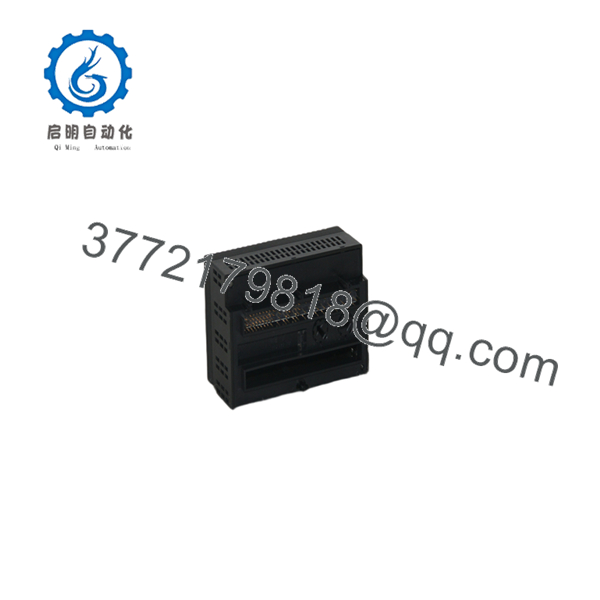
IC200ALG264H
5. Installation & Configuration Guide
Stage 1: Pre-Installation Preparation (10–15 min) ⚠️ Safety First: Remove power from the VersaMax CPU and I/O station. Follow lockout/tagout. Wear an ESD wrist strap. Tools Required: ESD strap, screwdriver, shielded twisted-pair cable, jumper for range selection if needed. Data Backup: Record existing hardware configuration, %AI addressing, and scaling parameters from the PLC project.
Stage 2: Removing the Old Module (5–10 min)
- Confirm power is off.
- Disconnect field wiring from the terminal base or carrier. Label every wire.
- Release the module from the carrier and remove it. ⚠️ Keep the old module until the replacement is verified.
Stage 3: Installing the New Module (10–15 min)
- Verify the unit is marked IC200ALG264H.
- Install the module onto a compatible VersaMax carrier/terminal base.
- Set the range jumper: no jumper = 4–20 mA; jumper installed = 0–20 mA.
- Connect shielded twisted-pair field wiring to the appropriate terminals. Ground shields at one end only.
- Re-apply power. Self-Checklist: [ ] Correct carrier [ ] Range jumper set [ ] Wiring and shielding correct [ ] Module fully seated.
Stage 4: Power-On & Testing (15–30 min)
- Confirm the OK LED is on.
- In the PLC hardware configuration (Machine Edition / Logic Developer), verify the module is recognized and %AI addresses are assigned.
- Apply known current signals (e.g., 4 mA, 12 mA, 20 mA) and verify corresponding %AI values.
- Check open-wire diagnostics if using 4–20 mA.
- Scale the values in the application program as required. ⚠️ Troubleshooting Note: Incorrect readings are most often caused by wrong range jumper setting, missing shield, or open field wiring. No OK LED usually indicates backplane power or module seating issues.
6. Frequently Asked Questions (FAQ)
Q: Can the IC200ALG264H be hot-swapped? No. Always remove power from the VersaMax station before inserting or removing the module.
Q: Is the IC200ALG264 still in production? The VersaMax platform remains supported in many regions, but specific revisions such as H may be available only as surplus. Confirm current lifecycle status with Emerson for new projects.
Q: How is the input range selected? By a jumper on the carrier terminals. No jumper = 4–20 mA (default); jumper installed = 0–20 mA.
Q: Does the module require external power? No external power is required for the module itself. Power for 2-wire transmitters must be supplied from an external source.
Q: Why is the price lower than historical OEM list price? These are genuine surplus units from excess inventory. They are original GE/Emerson modules that have never been installed in a running system. Functional testing and warranty are provided.
Q: What is the resolution in engineering units? Approximately 0.5 µA per count in 4–20 mA mode and 0.625 µA per count in 0–20 mA mode.
Q: Is open-wire detection available? Yes, but only when the module is configured for the 4–20 mA range.



