
 WhatsApp: +86 16626708626
 Email:
  Phone: +86 16626708626
Description
3. Key Technical Specifications
| Parameter | Specification |
| Manufacturer | GE Fanuc / Emerson Automation Solutions |
| Part Number | IC200MDL241 |
| Product Line | VersaMax I/O / PLC System Platform |
| Number of Input Points | 8 inputs configured in 1 isolated group |
| Nominal Input Voltage | 120 Vac |
| Input Voltage Range | 85 to 132 Vac (47 to 63 Hz) |
| On-State Voltage | 70 to 132 Vac |
| Off-State Voltage | 0 to 20 Vac |
| On-State Current | 5 to 15 mA (Typically 12 mA @ 120 Vac) |
| Off-State Current | 0 to 2.5 mA maximum |
| Input Filter Delay | On-delay: 10 ms maximum | Off-delay: 20 ms maximum |
| Backplane Power Consumption | 30 mA maximum @ 5 Vdc logic rail |
| Isolation Barrier | 250 Vac continuous / 1,500 Vac for 1 minute (field-to-logic) |
| Diagnostic Indicators | 1x Green OK LED | 8x Green Input State LEDs |
4. Product Introduction & Supply Chain Strategy
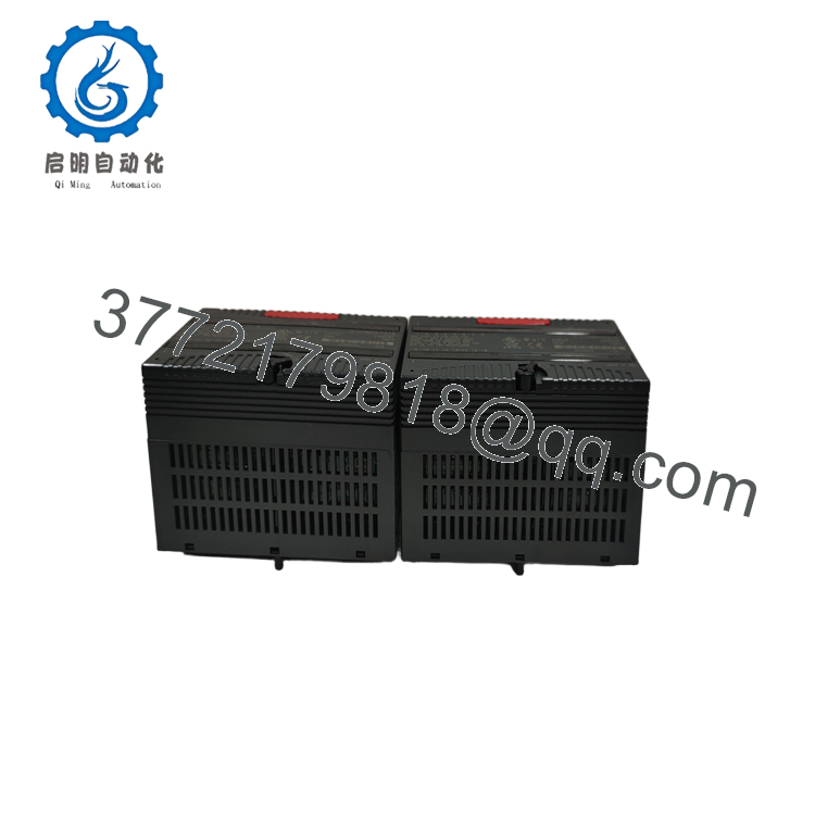
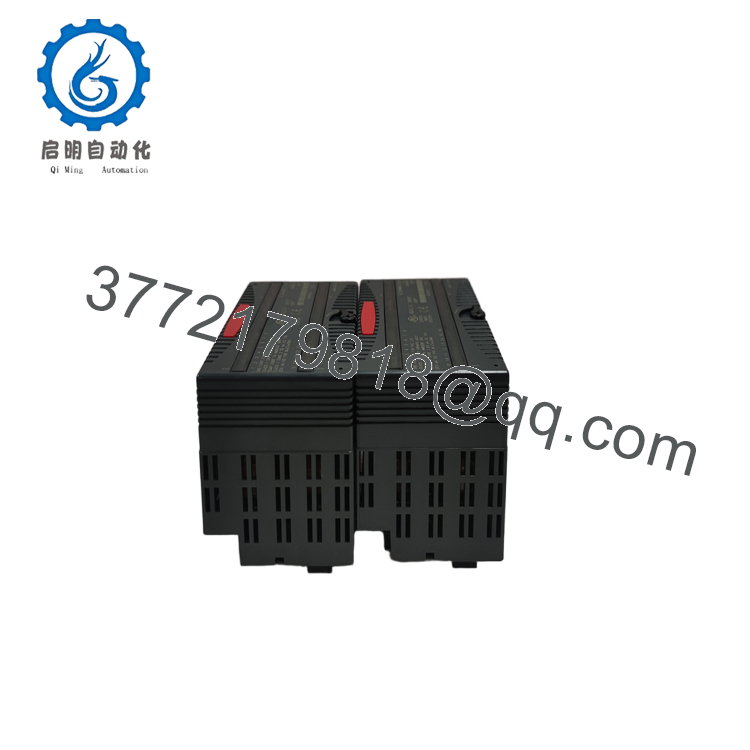
The GE VersaMax IC200MDL241 is an 8-point discrete AC input module designed to integrate directly with VersaMax PLC systems and remote Network Interface Units (NIUs). Operating at a nominal rating of 120 Vac, this module monitors ON/OFF states from physical field devices, such as limit switches, pushbutton operators, selector switches, and auxiliary relay contacts. It processes input signals through optical isolation barriers to protect the CPU backplane from voltage spikes and electromagnetic noise.
From a procurement and inventory lifecycle standpoint, stocking the IC200MDL241 as New Surplus is a highly effective way to manage total cost of ownership (TCO) and safeguard operational uptime. Relying on refurbished digital input cards introduces subtle risks; used modules are often exposed to physical and thermal stress that degrades their optocouplers and input resistors over time. This wear can result in intermittent switching delays, false-negative inputs, or failure to detect field transitions. Choosing a factory-sealed New Surplus module guarantees zero-hour OEM reliability and absolute signal isolation right out of the box.

- IC200MDL241
- IC200MDL241
5. Installation & Configuration Guide
Stage 1: Pre-Installation (Prep & Safety)
- System Power Isolation: Completely de-energize the targeted VersaMax rack. Open the circuit breakers for all external 120 Vac field supply lines running to the terminal carrier. Verify that all points read 0 Vac using a digital multimeter.
- Carrier Keying Audit: Check the companion IC200CHSxxx terminal carrier base. Ensure the mechanical keying index dial is matched for a discrete AC input module profile to prevent hardware damage during installation.
- ESD Protocol: Put on a grounded ESD wrist strap before unboxing the card to protect the internal logic from static damage.
Stage 2: Removal
- Latch Release: Press inward firmly on the flexible plastic release tabs located at the top and bottom edge flanges of the card housing.
- Module Extraction: Slide the module straight away from the terminal carrier base. Avoid rocking or twisting motions that might strain or bend the internal backplane connector pin matrix.
- Base Inspection: Clean any accumulated dust or particulate matter from the terminal base contacts before inserting the replacement card.
Stage 3: Installation (Clone & Seat)
- Module Seating: Align the housing guide tracks with the corresponding slots on the pre-wired terminal carrier base. Press the IC200MDL241 firmly onto the base until both the top and bottom locking clips click shut.
- Software Configuration Verification: Open your project files within Proficy Machine Edition. Ensure that the %I discrete address space mapped to this slot matches your legacy program reference tables.
Stage 4: Power-On & Testing
- Initial Power Application: Re-energize the external 120 Vac field supply, then apply primary power to the rack backplane assembly.
- LED Diagnostics Audit: Confirm the faceplate “OK” LED illuminates solid green, indicating a successful power-on self-test and active logic communication.
- Physical Loop Validation: Manually actuate one of the connected 120 Vac field switches (e.g., a local limit switch). Verify that the corresponding channel LED on the module front panel lights up green and the bit flips from 0 to 1 in your PLC software register.
6. Firmware/Software Versions & Upgrade Notes
The IC200MDL241 operates on hardware-defined logic and does not feature on-board flash memory or programmable CPU microcode. Hardware tracking is managed entirely by the physical board assembly and modification codes stamped on the PCB enclosure.
When integrating this card into legacy VersaMax networks, ensure your primary CPU or Network Interface Unit (such as the Profibus IC200BEM003) is running a firmware version that recognizes the module’s hardware profile. Most standard VersaMax configurations support the IC200MDL241 as a native module, meaning no special firmware updates are required during a drop-in replacement.
7. Frequently Asked Questions (FAQ)
- Why should I purchase a New Surplus IC200MDL241 instead of a refurbished unit? A refurbished module is a used component that carries hidden thermal strain from years of service inside industrial enclosures. Over time, internal optocouplers and resistor networks age, causing delayed input states or complete channel failures. This New Surplus card delivers zero operational hours, pristine 1,500 Vac field-to-logic isolation boundaries, and factory-certified reliability.
- Are the 8 inputs on this module individually isolated from each other? No. The 8 inputs on the IC200MDL241 share a common return path (neutral line) on the terminal base, forming a single isolated group of 8. While they are collectively isolated from the PLC’s internal logic circuitry, they cannot be wired to separate, out-of-phase AC power sources.
- Does this discrete input card require external power to operate? No, the module does not require a separate external auxiliary power supply to run its internal circuitry. The logic gates and communication bus draw 30 mA directly from the 5 Vdc PLC backplane rail. However, the field-side devices (pushbuttons, switches) must be supplied with an external 120 Vac line to trigger the input channels.
- Is it safe to hot-swap this module while the system is under power? Yes, the VersaMax hardware design supports hot-swapping I/O modules while the backplane is active, provided the terminal carrier base remains securely mounted. However, pulling an input module during production will instantly drop all eight telemetry points to zero, which can cause immediate trip faults in your active PLC control logic.
- What does a dark “OK” LED on the front panel indicate? The “OK” LED indicates the health of the module’s onboard logic. If it remains unlit when the PLC rack is powered, it suggests either a lack of 5 Vdc logic power from the backplane, an unseated module connection, or an internal hardware failure that caused the board to fail its power-on self-test.



