
 WhatsApp: +86 16626708626
 Email:
  Phone: +86 16626708626
Description
3. Key Technical Specifications
| Parameter | Specification |
|---|---|
| Manufacturer | GE Fanuc / Emerson Automation Solutions |
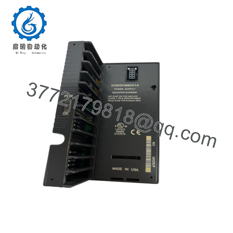
| Part Number | IC200PWB001A |
| Product Line | VersaMax I/O / PLC System Platform |
| Input Voltage Nominal | 24 Vdc |
| Input Voltage Range | 18 to 30 Vdc |
| Output Voltages (Backplane) | 5 Vdc and 3.3 Vdc regulated logic rails |
| Maximum 5 Vdc Output Current | 1.0 A maximum output |
| Maximum 3.3 Vdc Output Current | 0.25 A maximum output |
| Isolation Barrier | Non-isolated input-to-output architecture |
| Input Protection | Short circuit, overload, and reverse polarity safety circuits |
| Mounting Orientation | Snaps directly onto the left end of standard VersaMax I/O carrier bases |
| Diagnostic Indicators | 1x PWR LED (Green = Output logic voltages are normal and present) |
4. Product Introduction & Supply Chain Strategy
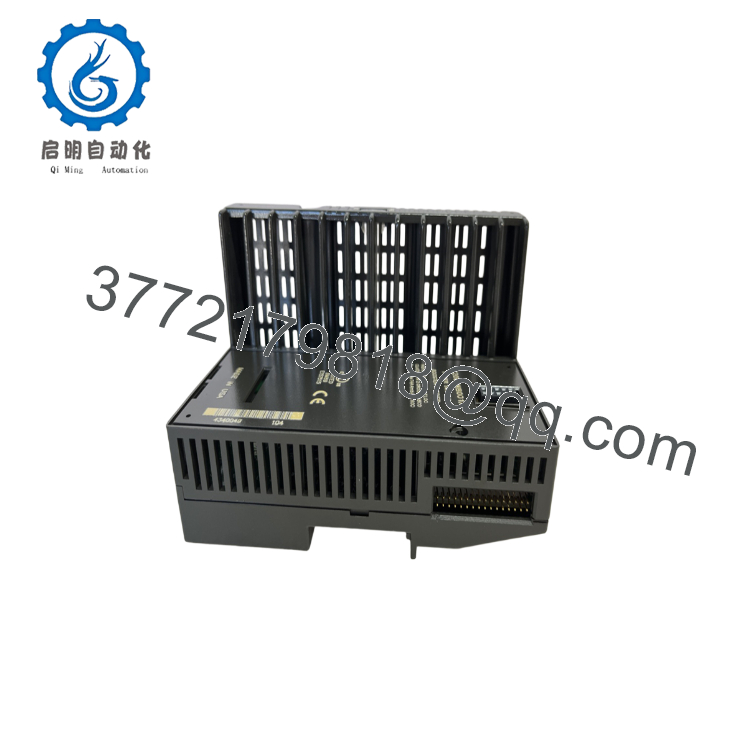
The GE VersaMax IC200PWB001A is a backplane expansion power supply module engineered to source auxiliary logic currents across local and remote I/O subrack channels. Accepting a nominal input of 24 Vdc, this module regulates and injects clean 5 Vdc (up to 1.0 A) and 3.3 Vdc (up to 0.25 A) power directly into the internal backplane logic rails. It serves as a power booster when a high-density cluster of analog, thermocouple, or specialty counter modules exceeds the baseline logic output capacity of the primary network interface unit (NIU) or CPU.
From an inventory asset management perspective, the IC200PWB001A is an essential insurance asset for critical facilities. Power modules are highly susceptible to internal component degradation, making refurbished units a significant Total Cost of Ownership (TCO) risk. Used or second-hand power supplies often suffer from latent thermal fatigue in their internal flyback transformers and smoothing capacitors, which can cause subtle voltage ripple or sudden logic drops. A sudden logic power failure will instantly crash the entire connected I/O rack, causing immediate plant downtime. This factory-sealed New Surplus power supply provides zero-hour components, ensuring complete voltage stability and continuous system uptime.

- IC200PWB001A
- IC200PWB001A
5. Installation & Configuration Guide
Stage 1: Pre-Installation (Prep & Safety)
- Main Power Isolation: Completely de-energize the incoming 24 Vdc primary power feed supplying the target subrack. Lock out and tag out the master distribution circuit breaker. Verify zero voltage at the incoming terminal block using a digital multimeter.
- Backplane Power Audit: Calculate the total current draw of all modules in the subrack using standard manual guidelines to confirm that total 5 Vdc consumption stays within the 1.0 A rating.
- ESD Protocol: Fasten a grounded ESD wrist strap prior to handling the module to safeguard internal power regulation semiconductors from static breakdown.
Stage 2: Removal
- Terminal Disconnection: Unscrew and unplug the 24 Vdc input wiring connector from the module base faceplate.
- Module Latches: Press down firmly on the integrated plastic release tabs at the top and bottom edge flanges of the module housing.
- Extraction: Slide the power supply straight forward and away from the I/O carrier base interface. Do not twist or torque the card during extraction to prevent damage to the backplane pins.
Stage 3: Installation (Clone & Seat)
- Carrier Alignment: Align the housing guide tracks of the new New Surplus IC200PWB001A with the left-most interface channels on the pre-wired VersaMax terminal carrier base.
- Seating the Module: Slide the power supply firmly onto the carrier base interface until the plastic retaining clips snap securely into position.
- Input Termination: Reattach the 24 Vdc incoming supply wires to the input terminal block, paying strict attention to correct positive (
+) and negative (-) terminal alignment.
Stage 4: Power-On & Testing
- Cold Insulation Verification: Run a quick continuity check across the input terminals to verify that no direct grounding paths or physical wire shorts occurred during terminal assembly.
- System Power Application: Close the primary distribution breaker to apply 24 Vdc input power to the module.
- LED Status Verification: Observe the front panel diagnostic display. The green “PWR” LED must illuminate solid, confirming that both the 5 Vdc and 3.3 Vdc internal logic lines are stable and successfully active across the backplane slots.
6. Firmware/Software Versions & Upgrade Notes
The IC200PWB001A operates entirely as a hardware-level analog voltage regulator and power distribution module. It does not feature an onboard microprocessor, programmable flash memory registers, or upgradable firmware stacks.
System compatibility is governed entirely by the physical backplane layout and structural configuration of the VersaMax carrier bases. When adding this power booster to an existing legacy system layout, no logic software upgrades or configuration setting updates are required within Proficy Machine Edition. The hardware automatically balances and delivers the required current paths down the backplane immediately upon seating and power application.
7. Frequently Asked Questions (FAQ)
- Why should I source a New Surplus IC200PWB001A rather than a refurbished unit? Power supply units generate internal heat during normal operation, which subjects their smoothing capacitors and transformer windings to constant thermal stress over time. A refurbished power module may look clean externally, but its internal components have already experienced significant thermal wear, making them prone to voltage drops or sudden failure under full load. This New Surplus module provides a zero-hour, factory-certified alternative that eliminates the risk of unexpected subrack crashes.
- Can this module be used to power external field loops or sensors? No. The IC200PWB001A is designed exclusively to provide internal logic operating power (5 Vdc and 3.3 Vdc) across the subrack backplane to power the internal processors of adjacent I/O cards. It does not have auxiliary output terminals for driving external 24 Vdc field current loops or field instrumentation.
- What does the “A” suffix at the end of the part number represent? The “A” suffix represents the functional factory artwork and assembly designator baseline. It confirms that the unit matches standard VersaMax electrical layouts, providing full drop-in backward and forward compatibility with all standard historical variants of the IC200PWB001 module line.
- Is it safe to hot-swap this power supply module while the PLC subrack is running? No. Attempting to remove or insert a backplane power supply module while the subrack is energized can cause severe electrical arcing across the data and power pins. This can permanently damage adjacent analog or processor cards and will cause an immediate loss of logic power, crashing the entire subrack. Always turn off the power before servicing.
- What does it mean if the “PWR” LED is unlit but the input breaker is closed? A dark “PWR” LED indicates that the internal 5 Vdc or 3.3 Vdc logic rails are not being generated successfully. This can be caused by an incoming supply voltage that falls below the minimum 18 Vdc threshold, an over-current short circuit condition on one of the adjacent I/O modules, or an internal hardware failure within the power supply module itself.



