
 WhatsApp: +86 16626708626
 Email:
  Phone: +86 16626708626
Description
Key Technical Specifications
| Parameter | Value |
|---|---|
| Catalog Number | IC670ALG620 |
| Product Family | GE Fanuc Field Control |
| Input Type | RTD analog input |
| Number of Channels | 4 independent channels |
| Wiring | 3-wire and 4-wire RTD |
| Supported RTD Materials | Platinum, nickel, nickel/iron, and copper |
| Resistance Ranges | 0–500 Ω and 0–3,000 Ω |
| Measurement Units | Resistance, tenths of °F, or tenths of °C |
| Digital Resolution | 15 bits plus sign |
| Scan Time at 60 Hz | Approximately 210 ms per point |
| Scan Time at 50 Hz | Approximately 230 ms per point |
| Input Excitation | Provided by the module; no external loop power required |
| Maximum Lead Resistance | 5 Ω per lead |
| Logic Supply Current | 190 mA maximum from the Bus Interface Unit supply |
| Operating Temperature | 0–55 °C ambient |
| Input-to-Ground Isolation | 1,500 VAC for 1 minute; 250 VAC continuous |
| Channel-to-Channel Isolation | 250 VAC continuous |
| Input Protection | 28 VDC or peak AC maximum; verify installation limits in GFK-1206 |
| Compatible Terminal Blocks | IC670CHS001, IC670CHS002, or IC670CHS003, depending on wiring format |
Product Introduction
The GE Fanuc IC670ALG620 is a four-channel Field Control RTD analog input module for independent 3-wire and 4-wire platinum, nickel, nickel/iron, or copper RTDs. It converts resistance measurements into digital temperature data for a GE Field Control station.
Each channel can be configured independently for resistance or temperature measurement, with selectable 0–500 Ω and 0–3,000 Ω ranges. The module provides its own RTD excitation current and reports open-wire, short-input, underrange, overrange, and high/low alarm conditions.
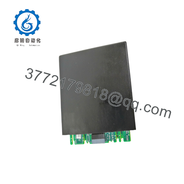
IC670ALG620
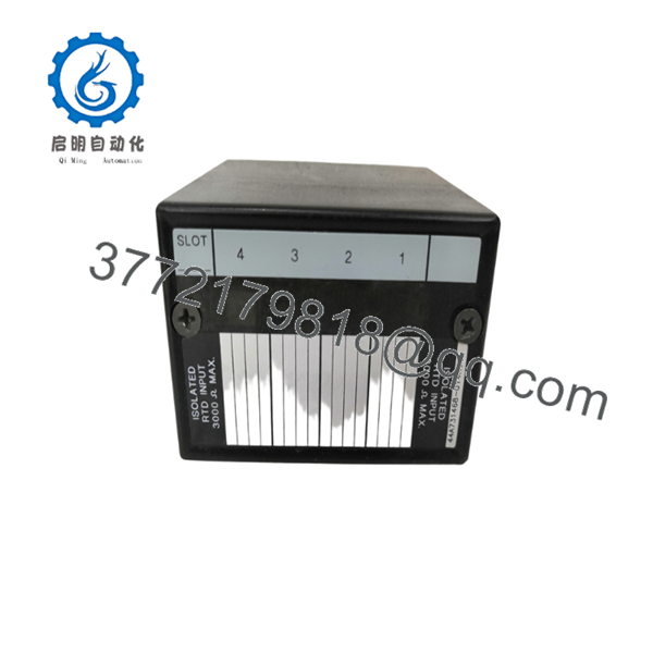
IC670ALG620
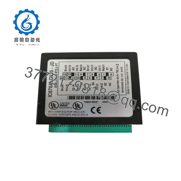
IC670ALG620
Troubleshooting Quick Reference
| Symptom | Possible Cause | Relevance to This Part | Quick Check Method | Recommendation |
|---|---|---|---|---|
| Module has no status indication | Missing BIU power, poor seating, or failed module | ✅ High | Verify Field Control power and measure the BIU supply; reseat the module with power removed | Check the Bus Interface Unit and terminal connection before replacing the module |
| All four channels read invalid data | BIU communication fault, configuration error, or module failure | ✅ High | Check Field Control diagnostics and confirm the module’s configured slot and address | Correct the BIU configuration and inspect the bus before condemning the IC670ALG620 |
| One channel reports open wire | Broken RTD lead, loose terminal, or incorrect 3-wire connection | ✅ High | Measure continuity from the RTD to the terminal block; inspect all three or four conductors | Repair the field wiring and verify terminal assignment before replacing the module |
| One channel reads high resistance | Wrong RTD type, open lead, or incorrect range selection | ✅ High | Disconnect the sensor and measure resistance with a calibrated multimeter; compare it with the configured range | Match the RTD type and range to the actual sensor |
| Temperature reading is consistently offset | Incorrect RTD material, lead resistance, wiring error, or calibration issue | ✅ Medium | Compare the sensor resistance with a reference thermometer and check all lead resistances | Verify sensor type and 3-wire compensation before replacing the module |
| Reading is unstable | Electrical noise, loose terminals, damaged sensor, or poor cable routing | ❌ Low | Monitor the channel while checking terminal torque, cable shielding, and sensor resistance | Correct wiring and shielding first; the module is not the first suspect |
| Multiple channels fluctuate together | Shared noise, BIU supply issue, or terminal block problem | ❌ Low | Check module supply voltage and compare all channels with the sensors disconnected | Inspect the terminal block, BIU supply, and grounding arrangement |
| Channel shows underrange or overrange | RTD resistance outside the selected range or wrong sensor type | ✅ High | Compare measured resistance with the configured 0–500 Ω or 0–3,000 Ω range | Select the correct range and RTD material in the Field Control configuration |
| All values are approximately twice or half the expected temperature | Incorrect engineering-unit interpretation or scaling | ❌ Low | Compare raw input data with the configured Celsius/Fahrenheit or resistance format | Correct PLC scaling and data interpretation before replacing hardware |
| Module fails after replacement | Incompatible terminal block, incorrect configuration, or wiring mismatch | ✅ Medium | Confirm the terminal block type, module slot, channel setup, and RTD wiring diagram | Verify the complete installation against GFK-1206 before commissioning |
If the fault remains unclear, contact technical support with photos of the module label, terminal block, RTD wiring, channel configuration, status LEDs, raw input values, and Field Control diagnostic logs.
Frequently Asked Questions (FAQ)
What does the GE Fanuc IC670ALG620 measure?
It measures resistance from four independent RTD sensors and converts each input into digital temperature or resistance data. It accepts 3-wire and 4-wire platinum, nickel, nickel/iron, and copper RTDs.
Does the IC670ALG620 require external loop power?
No. The module supplies the RTD excitation current internally, so the sensor loop does not require a separate external power supply.
Can I connect thermocouples to this module?
No. The IC670ALG620 is designed for RTD inputs, not thermocouples. Using a thermocouple will produce invalid measurements and may create configuration or diagnostic faults.
Which terminal block is required?
The Field Control system can use IC670CHS001 barrier terminals, IC670CHS002 box terminals, or IC670CHS003 connector terminals. Confirm the terminal block installed in the rack before ordering because the terminal assembly may not be included with the module.
Can I use a 2-wire RTD?
The published specification identifies 3-wire and 4-wire RTD operation. Do not assume that a 2-wire sensor will provide the specified accuracy, particularly when lead resistance is significant. Verify the application against GFK-1206 before installation.
Is the obsolete?
It is a legacy GE Fanuc Field Control module and may be available mainly through remaining inventory or industrial surplus channels. Ask the supplier to state the exact condition, date code, test procedure, warranty, and lead time.
What should I verify before replacing one?
Record the original RTD type, channel range, Celsius/Fahrenheit selection, terminal block type, slot location, and Field Control configuration. Also check the sensor lead resistance; the manual specifies a maximum of 5 Ω per lead.



