
 WhatsApp: +86 16626708626
 Email:
  Phone: +86 16626708626
Description
Key Technical Specifications
| Parameter | Value |
| Manufacturer | GE Fanuc |
| Part Number | IC693CHS397E |
| Hardware Revision | Revision E (Fully backward compatible with previous releases) |
| Series | Series 90-30 |
| Baseplate Type | CPU Main Baseplate (Rack 0) |
| Total Slot Capacity | 5 Slots (1 Power Supply + 1 CPU/Slot 1 + 4 Expansion/Option Slots) |
| Bus Interface Connector | 25-pin D-sub female connector (Right side) for I/O expansion cables |
| Module Compatibility | Standard I/O, High-Speed Counter, Motion, PCM, and Bus Controllers |
| Power Supply Slot | Leftmost dedicated slot (Compatible with IC693PWR321, PWR322, PWR330) |
| Mounting Format | Panel mount (4-bolt configuration) or DIN rail mounting |
| Maximum Expansion | Supports connection to up to 4 expansion or remote baseplates |
| Backplane Current | Supplied by the plug-in Series 90-30 Power Supply module |
Product Introduction & Supply Chain Strategy
The GE Fanuc IC693CHS397E is a 5-slot CPU main baseplate engineered for GE Series 90-30 PLCs. Serving as the primary chassis (Rack 0), it provides the physical mounting structure and high-speed backplane routing for the system CPU, power supply, and up to four discrete, analog, or specialty communication modules.
Securing this baseplate as New Surplus provides a crucial risk mitigation shield against system-level failures. Buying factory-fresh, unused backplanes eliminates the dangers of pin corrosion, micro-cracks in backplane circuit traces, and intermittent communication drops common in second-hand chassis pulled from active plant environments.
Installation & Configuration Guide
Stage 1: Pre-Installation (Prep & Safety)
- Perform strict Lock-Out/Tag-Out (LOTO) procedures on the power lines feeding the system power supply and field I/O devices.
- Put on a grounded anti-static wrist strap to protect internal backplane trace networks from ESD damage.
- Mark and take photos of all module slot positions, terminal blocks, power wiring, and the 25-pin expansion cable connection before disassembly.
Stage 2: Removal
- Unplug the 25-pin D-sub expansion cable from the right side of the baseplate (if local expansion racks are attached).
- Remove field wiring connectors, then extract the power supply, CPU, and all option cards from their respective slots.
- Loosen the four mounting bolts (or release the DIN rail clips) to detach the empty IC693CHS397 baseplate from the enclosure backpanel.
Stage 3: Installation (Clone & Seat)
- Mount the replacement IC693CHS397E securely onto the panel enclosure, ensuring clean metal-to-metal contact for ground continuity.
- Insert the power supply into the leftmost slot, the CPU into Slot 1, and remaining I/O modules into their exact historical slot positions.
- Connect the 25-pin expansion bus cable to the right-hand port and tighten the retaining thumbscrews.
Stage 4: Power-On & Testing
- Check electrical continuity between the baseplate grounding terminal and system safety ground using a multimeter.
- Energize the main power supply and verify that the CPU and Power Supply “OK” LEDs light up solid green.
- Connect via Proficy Machine Edition or Logicmaster 90 to confirm that all 5 slots report healthy diagnostic states without backplane parity errors.
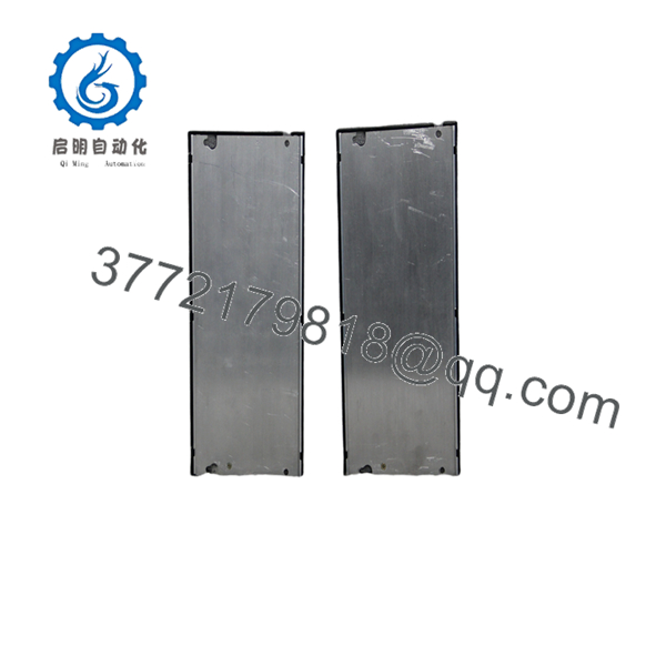
IC693CHS397E
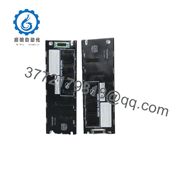
IC693CHS397E
Firmware/Software Versions & Upgrade Notes
- Revision Compatibility: The “E” suffix indicates the physical board manufacturing revision. Hardware Revision E is fully backward compatible with all earlier revisions (A through D) of the IC693CHS397 baseplate.
- CPU Support: Supports all modular Series 90-30 CPUs (such as CPU331, CPU341, CPU350, CPU360, CPU364, and CPU374). Embedded CPUs (e.g., CPU311, CPU313, CPU323) sit directly on the board and are restricted to specific baseplate models.
- System Limits: If this main baseplate is connected to expansion baseplates via the 25-pin D-sub port, ensure the total expansion cable length across the system does not exceed 50 feet (15 meters) to prevent backplane timing faults.
Frequently Asked Questions (FAQ)
Is this IC693CHS397E baseplate brand new or a pulled/refurbished unit?
This product is a Brand New Surplus unit. It is not used, not pulled from a decommissioned plant, and not refurbished. All modules undergo rigorous quality verification to ensure OEM-level reliability.
Why is buying New Surplus so critical for baseplate chassis?
Baseplates route high-speed backplane signals and power distribution to every card in the rack. Refurbished or pulled baseplates often carry hidden damage, such as bent card-edge connector pins, micro-cracks from thermal stress, or oxidation on copper contacts. Sourcing New Surplus guarantees 100% connector spring retention and zero prior thermal exposure.
What quality control procedures are completed prior to shipment?
Every IC693CHS397E undergoes a full quality assurance check. This includes anti-counterfeit serial verification, physical inspection of all 5 slot card-edge connectors, ground continuity checks, and live power-on bus testing on a Series 90-30 diagnostic bench.
What is the difference between an IC693CHS397 (5-slot) and an IC693CHS391 (10-slot) baseplate?
The IC693CHS397 provides 5 total slots (Power Supply + CPU + 4 Option Slots) for compact enclosure spaces. The IC693CHS391 provides 10 total slots (Power Supply + CPU + 9 Option Slots). Both serve as CPU Main Baseplates (Rack 0) and support identical CPU and I/O modules.
Does the IC693CHS397E require a DIP switch setup for rack numbering?
No. The CPU Main Baseplate is automatically designated as Rack 0 by the CPU. Rack numbering for external expansion baseplates (Racks 1 through 4) is set via DIP switches on the expansion cable adapters plugged into the 25-pin bus port.
What warranty coverage is provided with this New Surplus unit?
This baseplate comes with a full 1-year functional warranty. If any operational defect or connection fault occurs during normal use within 12 months of purchase, we will immediately send a replacement unit from our active buffer inventory.



