
 WhatsApp: +86 16626708626
 Email:
  Phone: +86 16626708626
Description
Key Technical Specifications
| Parameter | Value |
|---|---|
| Manufacturer | GE Fanuc |
| Model | IC693MDL655E |
| Product Series | Series 90-30 |
| Module Type | 24 VDC Discrete Input |
| Number of Inputs | 32 |
| Input Groups | 4 groups of 8 |
| Logic Type | Positive or Negative Logic |
| Nominal Input Voltage | 24 VDC |
| Input Voltage Range | 0 to 30 VDC |
| On-State Voltage | 11.5 to 30 VDC |
| Off-State Voltage | 0 to 5 VDC |
| Typical Input Current | 7.0 mA |
| Minimum On-State Current | 3.2 mA |
| Maximum Off-State Current | 1.1 mA |
| On Response Time | 2 ms maximum |
| Off Response Time | 2 ms maximum |
| Field-to-Logic Isolation | 1,500 V |
| Group-to-Group Isolation | 250 V |
| Backplane Current | 195 mA maximum @ 5 VDC |
| Isolated 24 VDC Current | 224 mA typical |
| Field Connection | Two 24-pin connectors |
| Compatible Cables | IC693CBL327, IC693CBL328 |
| Operating Temperature | 0 to 60 °C (32 to 140 °F) |
| Storage Temperature | -40 to 85 °C (-40 to 185 °F) |
| Module Width | Single Series 90-30 I/O slot |
The module provides 32 inputs divided into four isolated groups of eight. Each group has a shared common, and the inputs can be wired for either positive or negative logic.
Product Introduction
The GE Fanuc IC693MDL655E is a Series 90-30 24 VDC discrete input module with 32 input points. It monitors field devices such as proximity sensors, limit switches, pushbuttons, auxiliary contacts, and other 24 VDC on/off signals. The four groups of eight inputs provide electrical isolation between groups.
This high-density module accepts 0 to 30 VDC signals and supports positive or negative logic. It uses two 24-pin front connectors rather than a conventional removable terminal block, so existing cable assemblies must be checked before replacement. IC693CBL327 and IC693CBL328 are identified as compatible pre-wired cables.
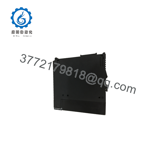
IC693MDL655E
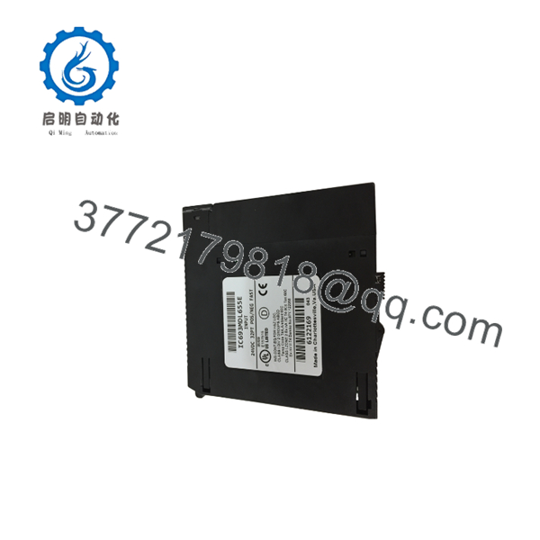
IC693MDL655E
Installation & Configuration Guide
Stage 1: Pre-Installation Preparation — About 10 Minutes
⚠️ Safety First
- Notify operations and obtain permission for the PLC shutdown.
- Place the controlled equipment in a verified safe state.
- Apply lockout/tagout procedures.
- Remove power from the PLC rack.
- Wait at least 5 minutes before handling the module.
- Use a multimeter to verify that hazardous field voltage has been removed.
⚠️ Do not assume a 24 VDC input module means the entire control cabinet is low voltage. Field wiring may be connected to separate higher-voltage circuits.
Tools Required
- ESD wrist strap
- PH1 screwdriver
- Digital multimeter
- Wire labels
- Smartphone or camera
- Suitable terminal/cable tools
Data Backup
Before removing the IC693MDL655E:
- Save the current PLC application.
- Record the exact rack and slot location.
- Photograph both 24-pin connectors.
- Record which connector serves each input group.
- Document all field-device wiring.
- Record the existing module revision.
⚠️ Photograph the connectors before disconnecting them. With 32 inputs, one misplaced conductor can create a misleading I/O fault.
Stage 2: Removing the Old Module — About 5 Minutes
- Remove the protective front cover if fitted.
- Label the field cables.
- Verify zero voltage before disconnecting the connectors.
- Disconnect the two 24-pin cable assemblies carefully.
- Release the module retention mechanism.
- Pull the IC693MDL655E straight out of the rack.
Inspect the removed module and rack for:
- Bent backplane contacts
- Contamination
- Heat discoloration
- Damaged connectors
- Loose cable hardware
⚠️ Keep the original IC693MDL655E beside the replacement until commissioning is complete.
Stage 3: Installing the New Module — About 10 Minutes
- Put on the grounded ESD wrist strap.
- Confirm the replacement marking:
GE Fanuc IC693MDL655E
- Confirm the revision is E, not simply an unspecified IC693MDL655.
- Verify the four input groups against the existing wiring.
- Insert the module into the designated Series 90-30 I/O slot.
- Press it firmly into position.
- Secure the module.
- Reconnect the two 24-pin field cables.
Configuration Clone Checklist
- revision verified
- Rack slot verified
- Group A wiring verified
- Group B wiring verified
- Group C wiring verified
- Group D wiring verified
- Cable connectors fully seated
- Positive/negative logic arrangement verified
⚠️ Do not substitute a cable based solely on connector appearance. Verify the cable part number and pin assignment.
Stage 4: Power-On & Testing — About 15 Minutes
Pre-Power Check
- Check the field supply with a multimeter.
- Confirm approximately 24 VDC where the application requires it.
- Check polarity.
- Verify there are no shorts between field conductors.
- Confirm the two module connectors are seated correctly.
Power-On Steps
- Power the PLC rack.
- Confirm the CPU reaches its normal operating state.
- Activate one field input at a time.
- Observe the corresponding module LED.
- Check the PLC input table.
- Compare the physical input state with the PLC software state.
- Test representative inputs from all four groups.
⚠️ If the field-device LED state is correct but the PLC input table remains unchanged, do not immediately replace the module. Check the cable, connector pinout, rack configuration, and PLC logic first.
Quick Fault Isolation
- No inputs in one group: Check that group’s common and cable.
- All 32 inputs failed: Check module seating, backplane, and field supply.
- One input failed: Check the individual field circuit and connector pin.
- Inputs remain ON: Check the actual field voltage against the 0 to 5 VDC OFF-state specification.
- Intermittent input: Inspect connector seating, cable condition, and field-device wiring.
Common Replacement Pitfalls From Field Experience
❗ 1. Confusing the Revision With the Base Part Number
The order is specifically for , not merely an unspecified IC693MDL655.
The IC693MDL655 family has been sold in multiple revisions, including B, C, E, F, G, H, K, and L according to current inventory references.
Avoidance: Photograph the original nameplate and request the exact revision when revision control matters.
❗ 2. Wrong Cable or Connector Assignment
This module uses two 24-pin connectors. One connector handles groups A/B and the other handles groups C/D.
I’ve seen plenty of high-density I/O problems caused by moving the correct cable to the wrong connector. The module powers up, so the mistake is easy to miss.
Avoidance: Mark the cables before removal and compare the connector arrangement with the original installation.
❗ 3. Confusing 24 VDC With 120 VAC Modules
The is a 24 VDC input module.
Do not replace it with an AC input card simply because the module occupies the same Series 90-30 slot.
The specified input range is 0 to 30 VDC, with 11.5 to 30 VDC recognized as the ON-state range.
❗ 4. Ignoring Positive/Negative Logic
The supports positive and negative logic arrangements.
Do not assume the replacement wiring can be changed without checking the existing circuit design.
Avoidance: Trace the common connection and field-device reference before changing wiring.
❗ 5. ESD Damage
Use a grounded wrist strap when handling the module.
The optical isolation and semiconductor input circuitry do not make the module immune to improper handling. Keep the replacement in its ESD packaging until installation.
Frequently Asked Questions (FAQ)
Q1: Can the be hot-swapped?
No. Treat the module as a power-off replacement in a standard Series 90-30 installation. Shut down the rack and verify the safe electrical state before removing it.
Q2: Is a 24 VDC input module?
Yes. It provides 32 discrete 24 VDC inputs and accepts an input range of 0 to 30 VDC. The module supports both positive and negative logic.
Q3: How are the 32 inputs organized?
The 32 inputs are divided into four isolated groups of eight. Each group has a common connection. This arrangement matters when troubleshooting field power distribution and grounding.
Q4: Can I use ordinary terminal-block wiring with this module?
Not directly. The uses two 24-pin front connectors. Existing installations commonly use IC693CBL327 and IC693CBL328 pre-wired cable assemblies. Check the actual cable and pinout before ordering a replacement.
Q5: Will replacing erase my PLC program?
Replacing the I/O module itself does not normally erase the PLC application stored in the CPU. However, save the current PLC project before shutdown and verify the hardware configuration after replacement.
Q6: Is obsolete?
The Series 90-30 platform is a legacy system, and current suppliers identify the IC693MDL655 family as discontinued/obsolete. Replacement stock is therefore typically sourced as new surplus, factory-sealed inventory, or tested used/refurbished equipment rather than current OEM production.
Q7: Why can two listings have very different prices?
Condition and revision traceability make a major difference.
A supplier may list the same part number as:
- Factory Sealed: Original factory packaging and seal.
- New Original / New Surplus: Unused inventory, packaging condition may vary.
- Refurbished (tested): Previously installed equipment that has been inspected and function tested.
- Used: Previously installed equipment with condition and testing scope defined by the supplier.
For a critical spare, ask for the actual nameplate photo, revision letter, test scope, warranty period, and available stock quantity before placing the order. Current listings show that is available in both used and surplus forms, illustrating why condition needs to be confirmed rather than assumed.



