
 WhatsApp: +86 16626708626
 Email:
  Phone: +86 16626708626
Description
Key Technical Specifications
| Parameter | Value |
| Manufacturer | GE Fanuc |
| Part Number | IC693MDL732 |
| Series | Series 90-30 |
| Module Type | Discrete Solid-State Output Module |
| Output Channels | 8 Points |
| Voltage Category | 12/24 V DC Positive Logic (Sourcing) |
| Operating Voltage Range | 12 to 30 V DC |
| Output Current | 0.5 A maximum per point (2.0 A maximum per common group at 60°C) |
| Inrush Current | 2.0 A peak for 10 ms |
| Output Leakage Current | 1 mA maximum |
| On-State Voltage Drop | 1.2 V DC maximum at full load |
| Response Time | 2 ms maximum On / 2 ms maximum Off |
| Backplane Power Draw | 55 mA at 5 V DC (plus external load power) |
Product Introduction & Supply Chain Strategy
The GE Fanuc IC693MDL732 is an 8-point solid-state output module designed for Series 90-30 PLCs. Delivering 12/24 V DC positive logic (sourcing) outputs at up to 0.5 A per point, it is optimized for high-duty-cycle industrial applications driving solenoid valves, pilot lights, indicators, motor starter coils, and control relays.
Securing the IC693MDL732 as New Surplus provides key supply-chain security for facilities running active Series 90-30 control architectures. Sourcing factory-fresh, uninstalled original inventory eliminates the elevated risks of switching transistor thermal stress, optocoupler breakdown, and terminal block wear common in second-hand parts, preserving control system reliability without requiring costly PLC retrofits.
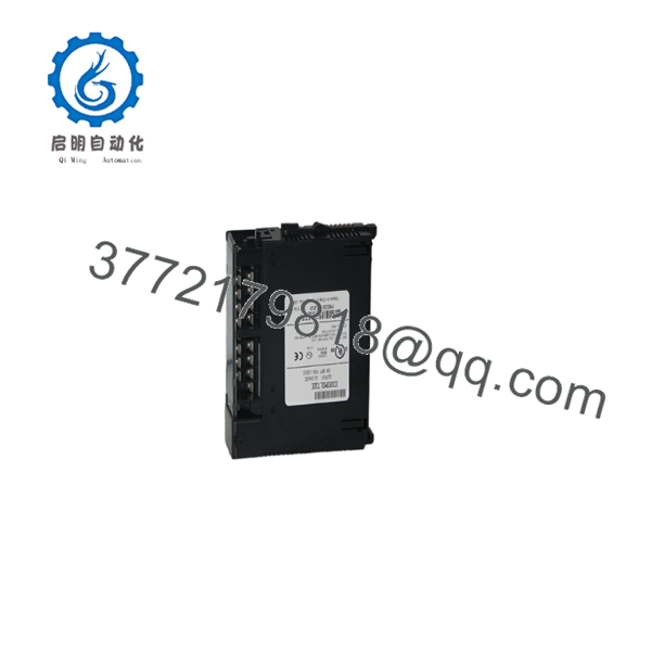
IC693MDL732
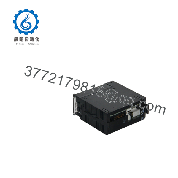
IC693MDL732
Installation & Configuration Guide
Stage 1: Pre-Installation (Prep & Safety)
- Execute Lock-Out/Tag-Out (LOTO) procedures on the PLC main rack power supply and field output power supply.
- Wear an anti-static grounded wrist strap to protect internal solid-state driver circuitry from ESD damage.
- Confirm that field load voltage (12–24 V DC) and total group current match module operating ratings.
Stage 2: Removal
- De-energize the PLC baseplate rack.
- Open the front cover door, loosen the top and bottom terminal assembly screws, and swing the hinged 20-terminal connector block off the module.
- Squeeze the release levers at the top and bottom of the module card and slide it straight forward out of the baseplate slot.
Stage 3: Installation (Seat & Wire)
- Align the rear card edge of the replacement IC693MDL732 with the slot guide rails of any available I/O slot in a Series 90-30 baseplate.
- Press firmly on the top and bottom face of the module until both retaining latches click locked.
- Snap the pre-wired 20-terminal block onto the front connector housing and tighten the top/bottom securing screws.
Stage 4: Power-On & Testing
- Reapply main power to the PLC rack and the 24 V DC field output supply.
- Check that the “MODULE OK” status LED lights solid green.
- Force output bits via Proficy Machine Edition or cycle system logic to verify corresponding output point LEDs (A1–A8) and field load actuation.
Firmware/Software Versions & Upgrade Notes
- Software Configuration: Configured using Proficy Machine Edition (PME), VersaPro, or Logicmaster 90. Simply allocate 8 bits in the
%Qdiscrete output memory table for the slot position. - Positive Logic Operation: Outputs supply positive voltage (+24 V DC) to the field load when turned ON. The load common must be tied to 0 V DC (-).
- Slot Compatibility: Can be installed in any available I/O slot of an IC693 Main, Expansion, or Remote baseplate.
Frequently Asked Questions (FAQ)
Is this IC693MDL732 output module brand new or pulled from a used rack?
This product is a Brand New Surplus unit. It is not used, not pulled from a decommissioned machine, and not refurbished. All modules undergo complete quality testing to verify original factory performance.
What is the advantage of sourcing New Surplus for solid-state output modules like the IC693MDL732?
Solid-state output cards experience continuous thermal stress across switching transistors when driving inductive loads (solenoids, contactors). Used or refurbished modules often suffer from silicon breakdown, increased leakage current, or degraded optical isolation. Buying New Surplus ensures 100% remaining component life and clean, fast switching.
What quality control steps are completed prior to shipment?
Every undergoes strict QC validation, including serial number tracking, physical backplane connector inspection, terminal screw torque checks, and live test rack verification under load to confirm channel switching and status LED operation.
What is the difference between positive logic (sourcing) and negative logic (sinking) outputs?
In positive logic (sourcing) modules like the , the output point switches +24 V DC to the field load. In negative logic (sinking) modules, the output point connects the field load to 0 V DC (ground).
Do I need to remove field wiring when replacing an existing ?
No. The module uses a removable 20-terminal block. You can unbolt the wired terminal assembly from the old module and attach it directly to the new unit without disturbing individual field wires.
What warranty coverage is included with this New Surplus output card?
This module includes a full 1-year functional warranty. If any operational defect or hardware failure occurs during normal use within 12 months, we will immediately supply a replacement unit from our active buffer inventory.



