
 WhatsApp: +86 16626708626
 Email:
  Phone: +86 16626708626
Description
Key Technical Specifications
| Parameter | Value |
|---|---|
| Manufacturer | GE Fanuc |
| Model Number | IC693MDL930 |
| Product Series | Series 90-30 |
| Module Type | Discrete Relay Output Module |
| Number of Outputs | 8 |
| Output Configuration | Individually isolated Form A, normally open |
| Nominal Output Voltage | 24 VDC / 120 VAC / 240 VAC |
| DC Operating Voltage | 5–30 VDC |
| AC Operating Voltage | 5–250 VAC, 50/60 Hz |
| Maximum Resistive Load | 4 A per output |
| Pilot Duty Rating | 2 A per output |
| Minimum Load | 10 mA |
| Maximum Module Load | 20 A for UL installations |
| Maximum Inrush Current | 5 A |
| Field-to-Logic Isolation | 1,500 VAC |
| Point-to-Point Isolation | 250 VAC continuous |
| Relay Response Time | 15 ms maximum ON/OFF |
| Switching Frequency | 20 cycles/minute |
| Backplane Current | 6 mA from 5 V bus; 70 mA from 24 V relay bus |
| Output Indicators | Individual LED indication |
| Fusing | None |
| Module Width | Single slot |
| Operating Temperature | 0 to 50 °C (32 to 122 °F) |
The IC693MDL930 provides eight individually isolated Form A relay outputs. Each output can switch 5–30 VDC or 5–250 VAC, with a 4 A maximum resistive-load rating per point.
Product Introduction
The GE Fanuc IC693MDL930 is a Series 90-30 discrete relay output module with eight individually isolated normally open Form A contacts. It is used to switch external loads such as motor starters, solenoids, contactors, and indicator circuits where electrical isolation between output points is required.
Each relay contact handles up to 4 A for resistive loads and operates across 5–30 VDC or 5–250 VAC at 50/60 Hz. Because each channel is individually isolated, the module is useful where different output circuits operate at different field voltages.
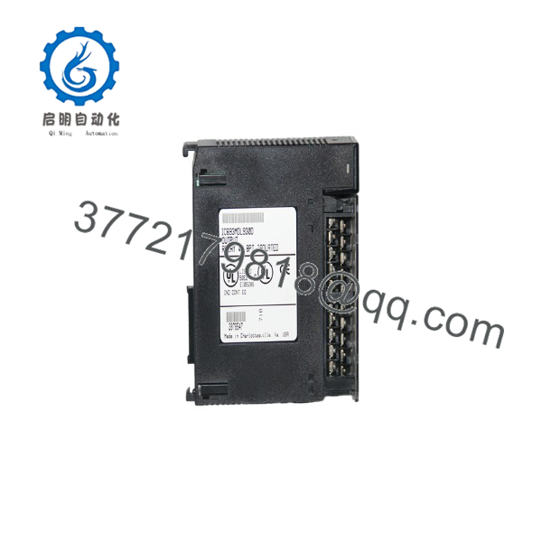
IC693MDL930
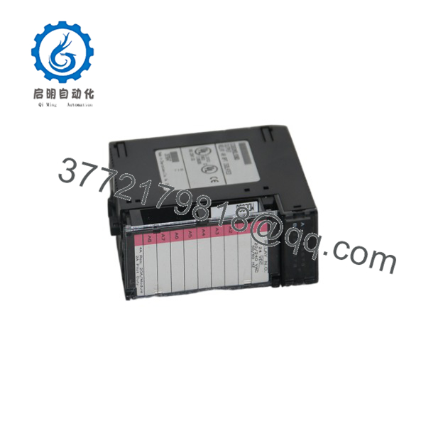
IC693MDL930
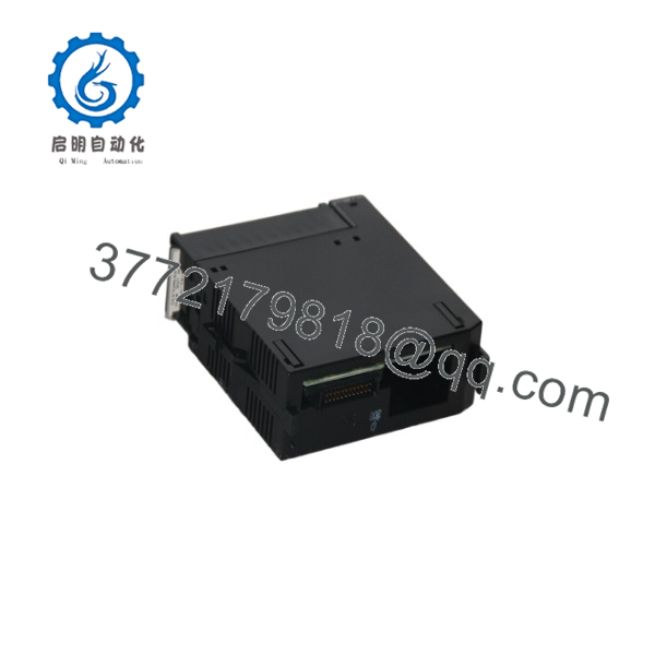
IC693MDL930
Installation & Configuration Guide
Stage 1: Pre-Installation Preparation — About 10 Minutes
⚠️ Safety First
- Notify operations before shutting down the PLC.
- Place the controlled equipment in a verified safe state.
- Apply lockout/tagout procedures.
- Remove power from the Series 90-30 rack.
- Wait at least 5 minutes for stored energy to discharge.
- Verify field-side voltage with a multimeter.
⚠️ Rack power removal does not necessarily remove voltage from external relay circuits. The IC693MDL930 can switch up to 250 VAC, so verify each field circuit separately.
Tools Required
- ESD wrist strap
- PH1 screwdriver
- Digital multimeter
- Wire labels
- Smartphone or camera
- Insulated hand tools suitable for the field voltage
Data Backup
Before removing the existing module:
- Save the current PLC application.
- Record the rack and slot position.
- Photograph the complete terminal wiring.
- Identify the load connected to each of the eight outputs.
- Record field voltage for each circuit.
- Photograph the module nameplate and revision.
Stage 2: Removing the Old Module — About 5 Minutes
- Open the module front cover.
- Label every output conductor.
- Verify zero voltage on each field circuit.
- Disconnect the field wiring.
- Release the module retention mechanism.
- Pull the module straight out of the rack.
Inspect:
- Backplane contacts
- Terminal connections
- Signs of relay overheating
- Corrosion
- Damaged insulation
- Loose field wiring
⚠️ Keep the old IC693MDL930 available until every output has been tested.
Stage 3: Installing the New Module — About 10 Minutes
- Put on a grounded ESD wrist strap.
- Verify the replacement marking:
GE Fanuc IC693MDL930
- Confirm that all eight outputs are individually isolated Form A contacts.
- Compare the replacement terminal layout with the original module.
- Insert the module into the Series 90-30 I/O slot.
- Seat it fully against the backplane.
- Secure the retention mechanism.
- Reconnect each field circuit according to the wiring documentation.
Configuration Clone Checklist
- Correct model
- Correct rack slot
- Output 1 wiring verified
- Output 2 wiring verified
- Output 3 wiring verified
- Output 4 wiring verified
- Output 5 wiring verified
- Output 6 wiring verified
- Output 7 wiring verified
- Output 8 wiring verified
- Field voltages verified
- Common/return wiring verified
⚠️ Relay outputs are dry-contact switching points. Do not treat the output terminals as a built-in 24 VDC power source. The external load circuit must provide its own field supply.
Stage 4: Power-On & Testing — About 15 Minutes
Pre-Power Check
- Check each field circuit for shorts.
- Verify the external supply voltage for each load.
- Confirm the load current.
- Check that no output exceeds the applicable current rating.
- Verify wiring against the original drawings.
Power-On Steps
- Power the PLC rack.
- Confirm the CPU reaches its normal operating state.
- Command one output at a time.
- Check the corresponding LED.
- Listen for relay operation where practical.
- Measure voltage at the load.
- Verify the connected device operates correctly.
- Test all eight outputs.
Quick Fault Isolation
- LED ON but load remains off: Check external field power, wiring, and load.
- LED OFF with PLC command active: Check PLC logic, rack configuration, and module seating.
- Relay operates but load does not: Check the external circuit through the Form A contact.
- One channel fails: Check that channel’s wiring and load before replacing the module.
- Multiple channels fail: Check rack seating and module power connections.
⚠️ Do not test relay outputs by shorting terminals. Use the actual load circuit or an appropriately rated test load.
Common Replacement Pitfalls From Field Experience
❗ 1. Assuming Relay Outputs Supply Voltage
They don’t.
The provides relay contacts. The external circuit supplies the voltage that the contact switches. The module accepts circuits from 5–30 VDC or 5–250 VAC.
This matters when troubleshooting. Seeing no voltage on an open relay contact does not automatically mean the module has failed.
Avoidance: Trace the complete circuit from field supply → load → relay contact → return.
❗ 2. Ignoring the 4 A Rating
The headline specification is 4 A per output for resistive loads. That does not mean every inductive load can be switched at 4 A.
The published pilot-duty rating is 2 A per point, and UL installations have a 20 A maximum total module load.
For motor starters, contactors, and solenoids, check the actual load characteristics and inrush current.
❗ 3. Forgetting That Relay Contacts Wear
Unlike a solid-state output, a mechanical relay contains physical contacts.
Repeated switching, inductive loads, arcing, and excessive inrush can shorten contact life.
The has a specified maximum switching frequency of 20 cycles per minute.
Avoidance: Check switching frequency and load type before using the module for rapid cycling.
❗ 4. Misdiagnosing a Stuck Relay
If an output remains electrically closed after the PLC command turns OFF, determine whether the relay contact is actually welded or whether an external circuit is feeding voltage back through the load.
Field check: Isolate the external circuit and measure the contact independently before condemning the module.
❗ 5. Mixing AC and DC Circuits Without Documentation
Because each output is individually isolated, different channels can be used for different field circuits within the module’s ratings. However, that flexibility increases the importance of clear labeling.
Do not assume all eight channels operate at the same voltage.
❗ 6. ESD and Mechanical Damage
Use ESD protection when handling the module, but also protect the relay terminals from mechanical impact.
Do not force the module into the rack. If the connector does not align, stop and inspect the slot and module.
Frequently Asked Questions (FAQ)
Q1: Can the be hot-swapped?
No. Treat the module as a power-off replacement in a standard Series 90-30 installation. Remove rack power and independently verify that all external field circuits are de-energized before disconnecting the module.
Q2: How many outputs does provide?
It provides eight individually isolated Form A normally open relay outputs. Each channel operates independently, which allows different field circuits to be isolated from one another.
Q3: Can the switch both AC and DC?
Yes. The published operating ranges are 5–30 VDC and 5–250 VAC at 50/60 Hz. The load and current rating still need to be checked for the particular application.
Q4: What is the maximum current per output?
The maximum resistive-load rating is 4 A per output. The published pilot-duty rating is 2 A per output. For UL installations, the maximum total module load is listed as 20 A.
Do not apply the 4 A resistive rating to every inductive application without checking the applicable load category.
Q5: Is the obsolete?
Yes. Current supplier references identify the as discontinued/obsolete. Replacement inventory therefore comes primarily from surplus, new-old-stock, used, or refurbished sources.
Q6: Will replacing erase my PLC program?
Replacing the I/O module itself does not normally erase the application program stored in the PLC CPU. Nevertheless, save the PLC project before shutdown and verify the hardware configuration after replacement.
Q7: Why can listings have different prices and conditions?
Because legacy inventory is sold in different conditions. Current listings show examples ranging from brand-new units to other inventory with different availability and revision information.
For a critical spare, request the actual nameplate photo, revision, condition, test scope, warranty period, and available quantity before ordering.



