
 WhatsApp: +86 16626708626
 Email:
  Phone: +86 16626708626
Description
3. Key Technical Specifications
| Parameter | Value |
| Microprocessor Type | Intel Celeron M |
| Clock Processing Speed | 1.0 GHz |
| Total Volatile RAM | 64 Mbytes (Battery-backed) |
| Non-Volatile Flash Memory | 64 Mbytes user storage |
| Switchover Sweep Intercept | Maximum 1 logic scan / Minimum 3.133 ms |
| Redundancy Link Support | Up to 2 x IC695RMX128 / IC695RMX228 Sync Links |
| Maximum Synchronization List | Up to 2 Mbytes per sync sweep |
| Embedded Interfaces | 1 x RS-232 (COM 1 via RJ-45), 1 x RS-485 (COM 2 via 15-pin D-sub) |
| Supported Protocols | Modbus RTU Slave, SNP Slave, Serial I/O |
| Boolean Logic Execution Speed | 0.047 ms per 1,000 instructions |
| Hardware Slot Width | Occupies two (2) slots on universal baseplate |
| Current Draw | 1.0 Amp @ 3.3 VDC nominal / 1.2 Amps @ 5.0 VDC nominal |
| Programming Environments | Ladder Diagram (LD), Structured Text (ST), Function Block (FBD), C |
4. Product Introduction & Supply Chain Strategy
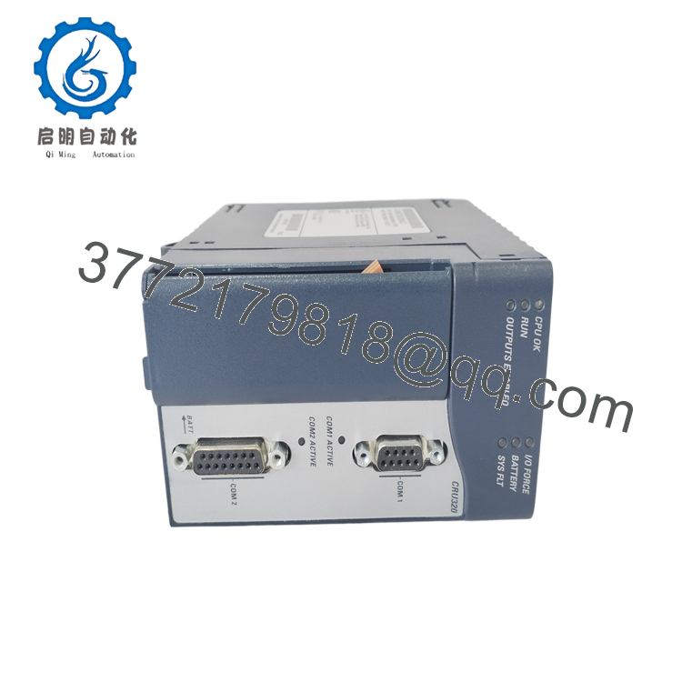
The GE Fanuc IC695CRU320 is a dual-slot, 1.0 GHz central processing unit specifically engineered to anchor hot-standby high-availability architectures within the PACSystems RX3i family. Working alongside specialized Redundancy Memory Xchange (RMX) modules, this unit continuously syncs memory structures twice per program sweep across paired primary and secondary racks. In the event of a fault, the processor triggers an automated control transfer within a single logic scan, ensuring continuous loop management in highly critical processes.
From a supply chain perspective, this redundancy controller represents a high-impact, low-turnover asset. It acts as an absolute insurance policy for operations where downtime can incur severe capital losses. Relying on refurbished processors compromises critical safety nets due to unseen component wear on the internal logic board. Securing a factory-sealed New Surplus module eliminates these vulnerabilities, guaranteeing clean startup registers and zero-hour reliability while bypassing high OEM distribution markups and long emergency procurement timelines.

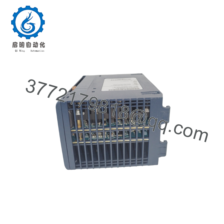
- IC695CRU320
- IC695CRU320
5. Installation & Configuration Guide
Stage 1: Pre-Installation (Prep & Safety)
Enforce complete lock-out/tag-out (LOTO) protocols across the universal backplane and all associated external field terminal connections. Put on a grounded ESD wrist strap before unboxing the unit. Prior to physical extraction, connect your laptop to the active controller port, compile a full diagnostic update, upload the current project configuration, and save a dedicated copy of the reference register tables in Proficy Machine Edition.
Stage 2: Removal
Unplug the active serial cables from the forward-facing COM 1 and COM 2 communication ports. Unlatch the auxiliary battery housing connection from the card face. Firmly depress the top and bottom module plastic retaining clips, then pull the processor straight out out of the universal rack slots, taking care to pull horizontally to avoid throwing the backplane PCI contacts out of alignment.
Stage 3: Installation (Clone & Seat)
Verify the internal hardware chassis pins on the back of the new IC695CRU320 are free of debris. Align the double-width casing tracks with the target baseplate slot positions (typically Slots 1 and 2). Slide the new module directly into the rack until both the upper and lower latching mechanisms click home securely. Reattach the dedicated communication links and plug in the fresh smart battery assembly.
Stage 4: Power-On & Testing
Apply system power to the primary baseplate power rail. Monitor the front-panel indicator matrix: the “CPU OK” and “Run” indicators must turn solid green after completing the baseline boot diagnostics. Connect your engineering station over the active serial port, clear the historical CPU error log, verify the redundancy configuration properties, and push down the matched project application blocks.
6. Firmware/Software Versions & Upgrade Notes
Redundancy control requires rigid firmware matching between paired IC695CRU320 processors to achieve stable synchronization handshakes.
- Version Parity: The primary and secondary CRU320 modules must execute the exact same firmware revision down to the minor build number. A mismatch will break the link, causing the system to fall back into simplex operation.
- RMX Coordination: Firmware baselines such as V7.18 introduce critical monitoring additions for the interface between the CPU and IC695RMX128/228 modules.
- Proficy Compliance: Ensure your Proficy Machine Edition software environment uses the correct version-specific device profiles. Forcing a configuration compiled under an updated target baseline into an older CPU platform can corrupt internal reference tables and induce continuous system faults.
7. Frequently Asked Questions (FAQ)
Can I run this processor as a standalone unit without a redundant partner?
Yes, the IC695CRU320 can run in simplex mode within a single rack configuration. If the secondary standby partner is absent or experiences a hardware stop, the primary unit executes all logic blocks independently. However, to leverage its full hot-standby capabilities, you must install a matched partner processor, twin racks, and RMX synchronization links.
Are these units brand new or repaired surplus?
This product is a Brand New Surplus unit. It is not used, not pulled from a decommissioned plant, and not refurbished. All modules undergo rigorous quality verification to ensure OEM-level reliability. Every processor is stored within sealed anti-static protective packaging, showing pristine gold edge connectors and zero track adjustments.
Can I install standard local I/O modules directly inside the redundant CPU rack?
No. Standard local I/O modules cannot be placed within the primary or secondary racks hosting the IC695CRU320 processors. The redundant architecture requires the CPU racks to remain dedicated to processing and synchronization. All field I/O must be located in separate expansion or remote drops linked via network interfaces like PROFINET or Genius networks.
How does the processor maintain logic variables during a main power failure?
The IC695CRU320 features 64 Mbytes of battery-backed RAM paired with an external lithium smart battery module (such as the IC695ACC302). This configuration maintains live register data and systemic memory states through power dips. Furthermore, the unit features 64 Mbytes of non-volatile flash memory, enabling permanent local backup archives of the application code.
What parameters determine an automatic switchover event?
The processor constantly monitors internal diagnostics, rack power supplies, and communication statuses. An automatic switchover to the backup controller occurs if the active unit experiences a CPU hardware fault, a complete loss of power, an explicit hardware configuration error, or if the logic program enters a STOP mode. The transfer executes seamlessly in less than one logic scan.



