
 WhatsApp: +86 16626708626
 Email:
  Phone: +86 16626708626
Description
3. Key Technical Specifications
| Parameter | Specification |
| Manufacturer | Horner APG (Co-developed / Distributed by GE Fanuc) |
| Part Number | HE693DAC420 |
| PLC Series Compatibility | GE Fanuc Series 90-30 Control Systems |
| Slot Allocation | Consumes 1 standard I/O slot on local or expansion baseplates |
| Number of Channels | 4 independent analog output channels |
| Output Loop Profile | 4 to 20 mA current source per channel |
| Digital Resolution | 12-bit binary converter layout (1 part in 4,096 scale) |
| External Power Requirement | 24 Vdc nominal loop supply (18 to 30 Vdc operating range) |
| Backplane Power Consumption | 35 mA at 5 Vdc drawn from the primary rack power rail |
| Isolation Barrier | 1,500 V RMS field-to-logic optical isolation |
| Update Rate Time | Under 4.0 ms for all 4 channels to process register updates |
| Maximum External Load | Supports up to 600 ohms per current loop channel at 24 Vdc |
4. Product Introduction & Supply Chain Strategy
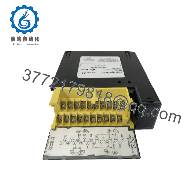
The HE693DAC420 is a 4-channel, 12-bit analog current output module designed as part of the GE Fanuc Series 90-30 PLC platform. Manufactured by Horner APG to seamlessly integrate into standard Series 90-30 baseplates, this source module translates numeric controller registers into precise 4–20 mA analog control loops. It functions as the primary interface for regulating key field hardware like variable frequency drives (VFDs), modulating control valves, I/P transducers, and analog chart recorders.
Because the Series 90-30 system has entered legacy maturity, the HE693DAC420 is a critical target for proactive risk mitigation. Relying on refurbished analog cards creates a significant Total Cost of Ownership (TCO) risk; second-hand modules often contain old digital-to-analog converter (DAC) components and worn optocouplers that introduce subtle signal drift or channel crosstalk. Such errors can lead to unexpected valve movements or unstable motor speeds. This New Surplus module provides a clean, factory-calibrated solution that preserves 1,500 V bus isolation and ensures complete operational reliability.

- HE693DAC420
- HE693DAC420
5. Installation & Configuration Guide
Stage 1: Pre-Installation (Prep & Safety)
- Power Isolation: Completely shut down the Series 90-30 PLC rack supply line. Place safety locks on the main control breaker panel. Verify that the 24 Vdc external loop supply wiring registers 0 V before proceeding.
- Logic Verification: Confirm the active configuration mapping within Proficy Machine Edition or Logicmaster 90. Ensure that the %AQ memory registers are correctly allocated to the target slot.
- ESD Mitigation: Put on a grounded ESD wrist strap before unboxing the new card to avoid static damage to the internal 12-bit converter array.
Stage 2: Removal
- Terminal Disconnection: Unscrew and remove the front terminal block door assembly from the module body. Do not pull individual field wires.
- Card Unlock: Press down firmly on the plastic release latch tabs at the top and bottom edge flanges of the card housing.
- Extraction: Pull the card straight outward along the baseplate guide grooves to avoid scratching the rear connector interfaces.
Stage 3: Installation (Clone & Seat)
- Baseplate Engagement: Align the top and bottom alignment channels of the new New Surplus HE693DAC420 with the empty slot rails on the baseplate.
- Card Seating: Push the card firmly into the rack slot until the rear pins seat completely in the backplane bus socket and the plastic locking levers snap closed.
- Terminal Attachment: Reattach the pre-wired terminal block to the module faceplate. Ensure the block locks securely into position to prevent loose current-loop connections.
Stage 4: Power-On & Testing
- Cold Insulation Verification: Check the resistance between the field 24 Vdc supply lines and the chassis ground terminal to confirm no physical shorts exist.
- System Start: Flip the main rack power breaker back on and change the CPU status to RUN mode.
- Telemetry Diagnostics: Monitor the CPU module LEDs. The “OK” indicator on the HE693DAC420 faceplate must show solid green. Force an analog output level from your logic software to ensure the loop accurately delivers the targeted current (e.g., 12.0 mA at a 50% digital register command).
6. Firmware/Software Versions & Upgrade Notes
The HE693DAC420 relies on fixed, hardware-defined analog logic networks rather than field-upgradable firmware microcode. System compatibility is managed by matching the physical PCB hardware revision with your primary PLC CPU operating environment.
When deploying this card as a replacement within very old Series 90-30 systems (such as CPU 311 or 331 models running legacy Logicmaster 90 software), ensure your software layout recognizes Horner APG third-party modules as standard %AQ analog outputs. If you are replacing an early revision board with a newer version, double-check your external 24 Vdc wiring layout. Early revisions required specific external grounding on terminal pin 11, whereas newer models use internal isolation paths to minimize ground-loop noise.
7. Frequently Asked Questions (FAQ)
- Why is this card marked as both a GE Fanuc and a Horner APG product? Horner APG co-developed and manufactured several specialty analog, communication, and interface modules for the GE Fanuc Series 90-30 system. This board drops directly into standard 90-30 racks and operates on standard
%AQaddressing, offering full compatibility with original GE components. - Does this module function as a current loop “source” or “sink”? The HE693DAC420 is a sourcing analog module. It supplies the 4–20 mA current directly from its channels out to the connected field instruments using an external 24 Vdc auxiliary power feed. It does not act as a passive loop sink.
- What happens to the current loops if the PLC CPU drops into STOP mode? If the primary PLC rack loses communication or enters STOP mode, the HE693DAC420 defaults to dropping all 4 analog output channels down to a safe state of 0 mA (or 4 mA, depending on how your specific hardware configuration file is set up). This action ensures that connected devices, such as control valves, move to their pre-defined safe failure positions.
- Can I pull this module out of the rack while the baseplate power is turned on? No. The GE Fanuc Series 90-30 platform does not support hot-swapping I/O modules. Attempting to remove or insert a card while the rack is powered can cause electrical arcing across the backplane data pins, which can corrupt running CPU memory registers or permanently damage adjacent boards.
- How does buying New Surplus provide a lower Total Cost of Ownership (TCO) than a refurbished module? Refurbished analog cards often have aging internal component components that can lead to subtle measurement drift over time. This calibration drift can cause control valves to fluctuate or VFD inputs to misread. A New Surplus board provides a zero-hour component with factory-original calibration precision, eliminating the risk of unexpected diagnostic faults and process interruptions.



