
 WhatsApp: +86 16626708626
 Email:
  Phone: +86 16626708626
Description
3. Key Technical Specifications
| Parameter | Value |
|---|---|
| Manufacturer | GE Vernova Grid Solutions |
| Product Family | Hydran M2-X |
| Model | M2X-O1-S1-A1-B0-C0-D1-P2-G0-VC0-V0-E0-M0-L2 |
| Monitoring Technology | Online Dissolved Gas Analysis (DGA) |
| Sensor Type | Composite gas fuel-cell sensor |
| Measured Range | 25–2,000 ppm H₂ equivalent |
| Accuracy | ±10% of reading ±25 ppm |
| Response Time | Approximately 10 minutes (90% step response) |
| Analog Inputs | One 4–20 mA Analog Input Card |
| Digital Inputs | Dual Digital Input Card |
| Communication | Ethernet 10/100 Mbps, Modbus TCP/DNP3 |
| Local Ports | RS-232, Isolated RS-485 |
| Enclosure | Aluminum, NEMA 4X / IP56 |
| Mounting | 1.5 in. NPT gate valve |
| Operating Power | 90–132 VAC or 180–264 VAC, 47–63 Hz |
| Operating Temperature | -40 °C to +55 °C (ambient) |
| Weight | Approximately 7.5 kg |
4. Product Introduction
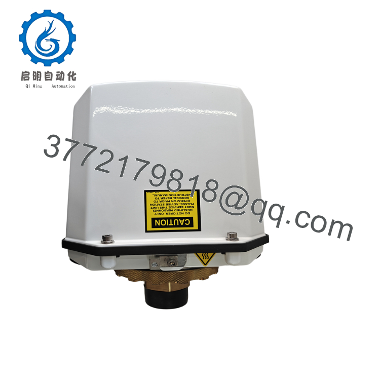
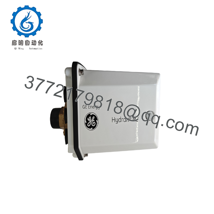
The GE Hydran M2X-O1-S1-A1-B0-C0-D1-P2-G0-VC0-V0-E0-M0-L2 is an online transformer monitoring system designed for continuous dissolved gas analysis (DGA) in mineral oil-filled power transformers. It continuously measures composite fault gases and transmits diagnostic data to asset management or SCADA systems using Ethernet-based industrial communication protocols.
This configuration includes a composite gas sensor, one 4–20 mA analog input module, dual digital inputs, and Ethernet communication using Modbus TCP/DNP3. It is intended for utilities that require continuous transformer condition monitoring without periodic manual oil sampling.

- M2X-O1-S1-A1-B0-C0-D1-P2-G0-VC0-V0-E0-M0-L2
- M2X-O1-S1-A1-B0-C0-D1-P2-G0-VC0-V0-E0-M0-L2
5. Installation & Configuration Guide
Stage 1 – Pre-Installation Preparation (20 Minutes)
⚠️ Safety First
- Notify system operations before removing the monitor.
- Verify transformer maintenance authorization.
- Apply Lockout/Tagout where required.
- Depressurize the valve if removal is necessary.
- Confirm oil temperature is within the manufacturer’s service limits.
Tools Required
- ESD wrist strap
- Fluke 115 multimeter
- Adjustable wrench
- Torque wrench
- Laptop with Hydran configuration software
- Ethernet cable
- Smartphone for installation photographs
Data Backup
Before removal:
- Export Hydran configuration.
- Record IP address and subnet.
- Save alarm thresholds.
- Record firmware revision.
- Photograph all wiring and terminal connections.
- Document analog scaling and digital input assignments.
Stage 2 – Removing the Existing Unit (20 Minutes)
- Disconnect AC power.
- Disconnect Ethernet and serial communications.
- Label every cable.
- Remove signal wiring.
- Close the transformer valve.
- Remove the monitor carefully from the valve connection.
Inspect:
- Valve threads
- Oil seal
- Connector pins
- Moisture ingress
- Enclosure condition
⚠️ Retain the original monitor until commissioning is successfully completed.
Stage 3 – Installing the New Unit (25 Minutes)
- Wear an ESD wrist strap.
- Verify the complete ordering code matches:
M2X-O1-S1-A1-B0-C0-D1-P2-G0-VC0-V0-E0-M0-L2
- Install the monitor onto the 1.5-inch NPT valve.
- Tighten according to the manufacturer’s torque specification.
- Connect AC power.
- Connect Ethernet.
- Connect analog and digital field wiring.
- Configure network parameters.
Installation Checklist
- Ordering code verified
- Valve fully tightened
- Ethernet operational
- Analog inputs verified
- Digital inputs tested
- Ground connection confirmed
Stage 4 – Startup & Commissioning (30–45 Minutes)
Pre-Power Inspection
- Verify supply voltage.
- Confirm grounding.
- Verify communication wiring.
- Inspect oil valve integrity.
Startup Procedure
- Energize the monitor.
- Verify LCD startup.
- Confirm self-diagnostics complete successfully.
- Connect using configuration software.
- Verify Ethernet communication.
- Confirm Modbus TCP or DNP3 communication.
- Verify gas readings.
- Test analog input scaling.
- Verify digital input operation.
⚠️ Troubleshooting Note
If communication fails:
- Verify IP addressing.
- Confirm network switch settings.
- Check firewall rules.
- Confirm Modbus TCP or DNP3 configuration matches the SCADA system.
SOP Quality Verification
1. Inbound Inspection & Traceability
Each Hydran M2-X undergoes:
- OEM label verification
- Serial number traceability
- Anti-counterfeit inspection
- Enclosure inspection
- Sensor integrity verification
- Connector inspection
Visual inspection confirms:
- No corrosion
- No impact damage
- No enclosure deformation
- No damaged connectors
2. Live Functional Testing
Testing should be completed using a dedicated GE Hydran M2-X transformer monitoring test bench.
Verification includes:
- Power-on self-test
- LCD verification
- Sensor response verification
- Ethernet communication
- RS-485 communication
- Analog input simulation
- Digital input simulation
- Continuous operation exceeding 24 hours
- Thermal stability verification
A formal Test Report should be generated.
Test videos and photographs should be available upon request.
3. Electrical Parameter Testing
Testing includes:
- 500 V insulation resistance (>10 MΩ)
- Ground continuity
- AC input verification
- Ethernet interface verification
- Analog input calibration
4. Firmware & Configuration Verification
Document:
- Firmware revision
- IP address
- Communication protocol
- Alarm configuration
- Sensor calibration data
- Digital input configuration
5. Final QC & Packaging
Final inspection includes:
- QC approval
- Anti-static packaging
- Protective foam inserts
- Heavy-duty shipping carton
- QC Passed label with inspection date
Technical Pitfalls & Survival Guide
❗ Ordering Code Mismatch
Hydran M2-X ordering codes define hardware features.
A monitor with a different communication option or sensor configuration may install mechanically but fail to integrate with the existing SCADA system.
Always compare the complete ordering code before purchasing.
❗ Communication Configuration
This configuration uses P2, which specifies Ethernet 10/100 Mbps with Modbus TCP/DNP3.
I have seen maintenance teams replace the hardware successfully but overlook the IP address and protocol settings. The monitor appeared healthy locally, yet the control room received no data because the network configuration was never restored.
❗ Valve Installation
Never overtighten the NPT connection.
Damaging the transformer valve or creating an oil leak can turn a simple monitor replacement into an extended outage.
Always follow the specified installation torque.
❗ Analog Input Scaling
This unit includes an A1 4–20 mA Analog Input Card.
Confirm scaling parameters after commissioning. Incorrect engineering-unit conversion can produce misleading transformer condition data and unnecessary maintenance actions.
❗ Electrostatic Discharge (ESD)
Although housed in a metal enclosure, the internal electronics remain sensitive to static discharge.
Always:
- Wear a grounded wrist strap.
- Use an ESD-safe work surface.
- Avoid touching internal circuit boards.
Keep these checks in mind and you’ll avoid the majority of commissioning issues encountered during Hydran M2-X replacement projects.
6. Frequently Asked Questions (FAQ)
Q1. What does this Hydran M2-X configuration monitor?
It continuously monitors dissolved fault gases in mineral-oil transformers using a composite gas sensor. It can also acquire additional operating data through optional analog and digital inputs.
Q2. What does the “P2” option mean?
The P2 option specifies an Ethernet 10/100 Mbps communication interface supporting Modbus TCP and DNP3 over TCP/IP.
Q3. Can this unit monitor ester-filled transformers?
No. The O1 configuration is intended for mineral oil transformers. Natural ester (NE) and synthetic ester (SE) applications require different ordering options.
Q4. Will replacing the monitor erase historical transformer data?
No. Historical data is typically stored within the monitoring software, historian, or SCADA platform rather than the field device itself. However, always back up the configuration before replacement.
Q5. Why is this configuration more expensive than the base model?
This unit includes optional hardware, including a 4–20 mA Analog Input Card (A1), Dual Digital Input Card (D1), and Ethernet communication (P2), which extend monitoring and integration capabilities beyond the standard configuration.
Q6. Why is aftermarket pricing lower than OEM pricing?
Many units become available through surplus inventory, utility modernization projects, or unused spare-part stock. Before purchasing, request:
- Serial number verification
- Sensor health report
- Functional test report
- Firmware revision
- Calibration records
- Warranty terms
Q7. What documentation should I request before shipment?
For critical transformer monitoring applications, request:
- Complete ordering-code verification
- Firmware revision record
- Sensor calibration report
- Ethernet communication test report
- 24-hour burn-in record
- QC inspection report
- ESD packaging confirmation
These records reduce commissioning risk and help ensure compatibility with existing transformer monitoring and asset management systems.



