
 WhatsApp: +86 16626708626
 Email:
  Phone: +86 16626708626
Description
3. Key Technical Specifications
| Parameter | Value |
|---|---|
| Model Number | IC200MDD844 |
| Manufacturer | GE Fanuc (Emerson) |
| Product Type | Mixed Digital Input/Output Module |
| Series | VersaMax I/O |
| Digital Inputs | 8 points |
| Digital Outputs | 8 points |
| Input Voltage | 24 VDC Nominal (Positive Logic) |
| Output Voltage | 24 VDC Nominal |
| Output Type | Positive Logic Transistor (Sourcing) |
| Maximum Output Current | 0.5 A per point |
| Total Output Current | 4 A maximum per module |
| Isolation | Optical isolation between field side and backplane |
| Backplane Power Consumption | Approximately 110 mA @ 5 VDC |
| LED Indicators | Individual I/O status LEDs and module OK LED |
| Typical Applications | Machine automation, conveyors, packaging systems, process control, OEM equipment |
4. Product Introduction
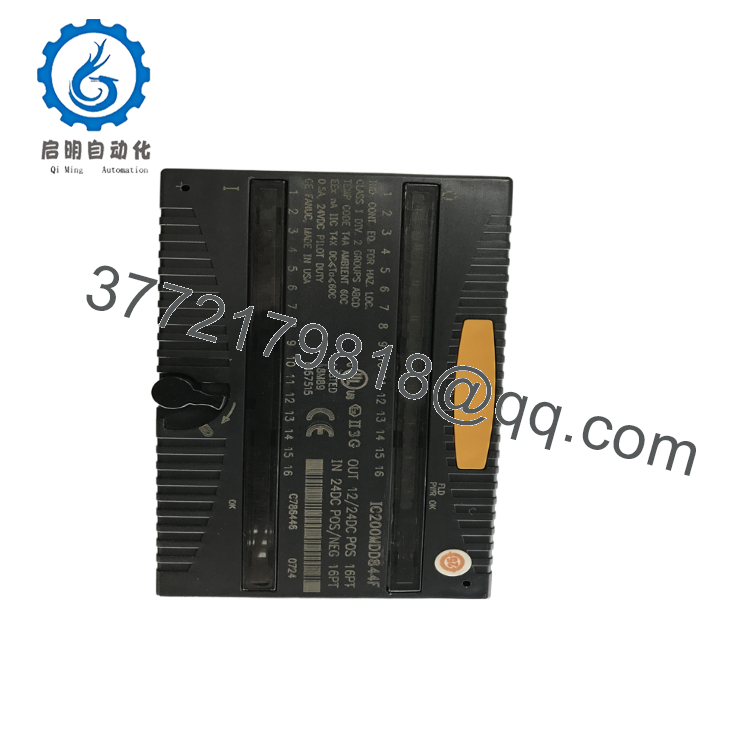
The GE IC200MDD844 is a VersaMax mixed digital I/O module that combines 8 discrete 24 VDC inputs and 8 discrete 24 VDC transistor outputs in a single compact module. It is designed for distributed I/O systems where both monitoring and control functions are required while minimizing cabinet space.
The module interfaces directly with sensors, pushbuttons, proximity switches, solenoid valves, contactors, relays, and indicator lamps. Optical isolation between the field wiring and the PLC backplane improves electrical noise immunity, making the IC200MDD844 suitable for demanding industrial automation environments such as manufacturing, material handling, water treatment, and packaging machinery.

- IC200MDD844
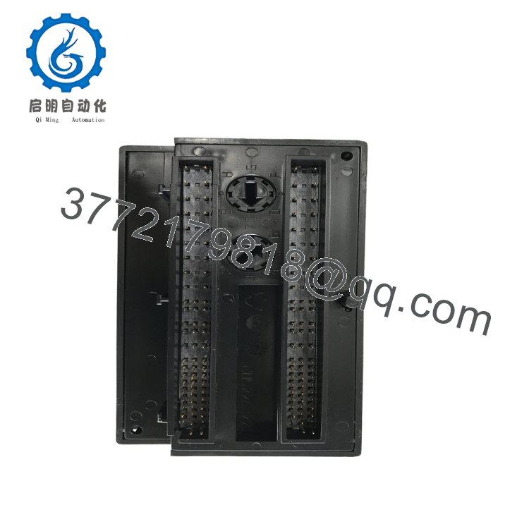
- IC200MDD844
5. Installation & Configuration Guide
Stage 1 – Pre-Installation Preparation (10 Minutes)
⚠️ Safety First
- Notify operators before shutting down the machine.
- Apply Lock-Out/Tag-Out (LOTO) procedures.
- Turn OFF power to the VersaMax station.
- Verify all field voltages are removed.
- Wear an ESD wrist strap during installation.
Required Tools
- Phillips screwdriver
- Digital multimeter
- ESD wrist strap
- Wire identification labels
- Wiring diagram
Backup Tasks
- Save the PLC project.
- Record the I/O addressing.
- Photograph all terminal wiring.
- Verify output load ratings.
Stage 2 – Removing the Existing Module
- Turn OFF system power.
- Label all field wiring.
- Remove the terminal assembly.
- Release the locking tab.
- Pull the module straight from the carrier.
- Inspect the carrier connector for damage.
⚠️ Do not discard the original module until the replacement has been fully commissioned.
Stage 3 – Installing the New Module
- Verify model IC200MDD844.
- Insert the module completely into the VersaMax carrier.
- Lock the retaining latch.
- Reconnect the field wiring.
- Verify all terminal connections.
- Restore the PLC configuration if necessary.
Installation Checklist
- ✔ Correct module installed
- ✔ Wiring verified
- ✔ Carrier locked
- ✔ Power connections secure
- ✔ I/O addressing confirmed
Stage 4 – Startup & Functional Test
Before Applying Power
- Verify 24 VDC field power.
- Check wiring polarity.
- Inspect output loads for shorts.
Startup Procedure
- Apply PLC power.
- Verify the module OK LED.
- Confirm all input LEDs respond correctly.
- Test each output individually.
- Verify operation from the PLC program.
- Confirm all field devices function normally.
Troubleshooting
- No input response: Check sensor power supply and wiring.
- Output not switching: Verify PLC logic and field power.
- Module fault LED ON: Inspect carrier connection and PLC diagnostics.
- Intermittent operation: Check grounding and cable shielding.
6. Frequently Asked Questions (FAQ)
Q1. How many I/O points does the IC200MDD844 provide?
The module provides 16 total digital I/O points, consisting of 8 discrete inputs and 8 discrete transistor outputs, all designed for 24 VDC positive-logic operation.
Q2. What types of field devices can be connected?
Typical devices include:
- Proximity sensors
- Photoelectric sensors
- Pushbuttons
- Limit switches
- Solenoid valves
- Relay coils
- Indicator lamps
- Small contactors
Q3. Is the IC200MDD844 an isolated module?
Yes. The module provides optical isolation between the field wiring and the VersaMax backplane, improving immunity to electrical noise and protecting the PLC from field-side disturbances.
Q4. Can the outputs drive solenoid valves directly?
Yes, provided the current drawn by each load does not exceed 0.5 A per output and the total module output current remains within the specified limit. Inductive loads should always be fitted with appropriate surge suppression devices.
Q5. Is this module still in production?
No. The IC200MDD844 belongs to the legacy GE Fanuc VersaMax product family. While active production has ended, New Surplus and professionally refurbished units remain available to support existing automation systems.
Q6. What is the most common installation mistake?
The most common issue is confusing positive-logic (sourcing) wiring with negative-logic (sinking) wiring. Verify that sensors, power supplies, and output devices are compatible with the module’s electrical configuration before energizing the system.
Q7. What should be verified before returning the equipment to service?
A commissioning engineer should confirm:
- Correct module model (IC200MDD844)
- Proper 24 VDC supply voltage
- Input and output wiring integrity
- Correct PLC I/O addressing
- Individual input and output operation
- Output current within specifications
- PLC diagnostics clear
- Stable operation of all connected field devices
Completing these checks before returning the machine to production helps ensure reliable digital I/O performance and minimizes unexpected downtime.



