
 WhatsApp: +86 16626708626
 Email:
  Phone: +86 16626708626
Description
3. Key Technical Specifications
| Parameter | Value |
|---|---|
| Model Number | IC200MDL742 |
| Manufacturer | GE Fanuc (Emerson) |
| Product Type | Discrete Digital Output Module |
| Series | VersaMax I/O |
| Number of Outputs | 32 Outputs |
| Output Groups | 2 groups of 16 outputs |
| Output Type | Positive Logic (Sourcing) Transistor |
| Rated Output Voltage | 24 VDC Nominal (18–30 VDC Operating) |
| Maximum Output Current | 0.5 A per point |
| Inrush Current | 2.0 A maximum for 100 ms |
| Output Response Time | 0.5 ms maximum (ON/OFF) |
| Protection | Electronic Short Circuit Protection (ESCP), Overcurrent Protection, Free-Wheeling Diodes |
| Isolation | Optical isolation from backplane; Group-to-Group Isolation 250 VAC continuous |
| Backplane Current Consumption | 150 mA @ 5 VDC |
| LED Indicators | OK, FLD PWR, Green Output Status LEDs, Amber Overload LEDs |
| Typical Applications | Solenoid valves, relays, contactors, indicator lamps, industrial automation |
4. Product Introduction
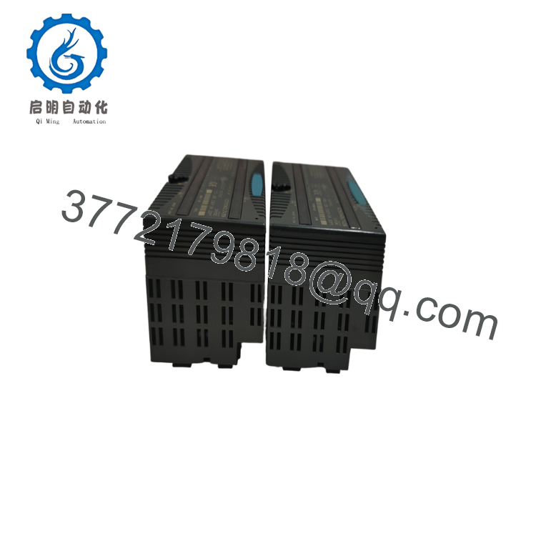
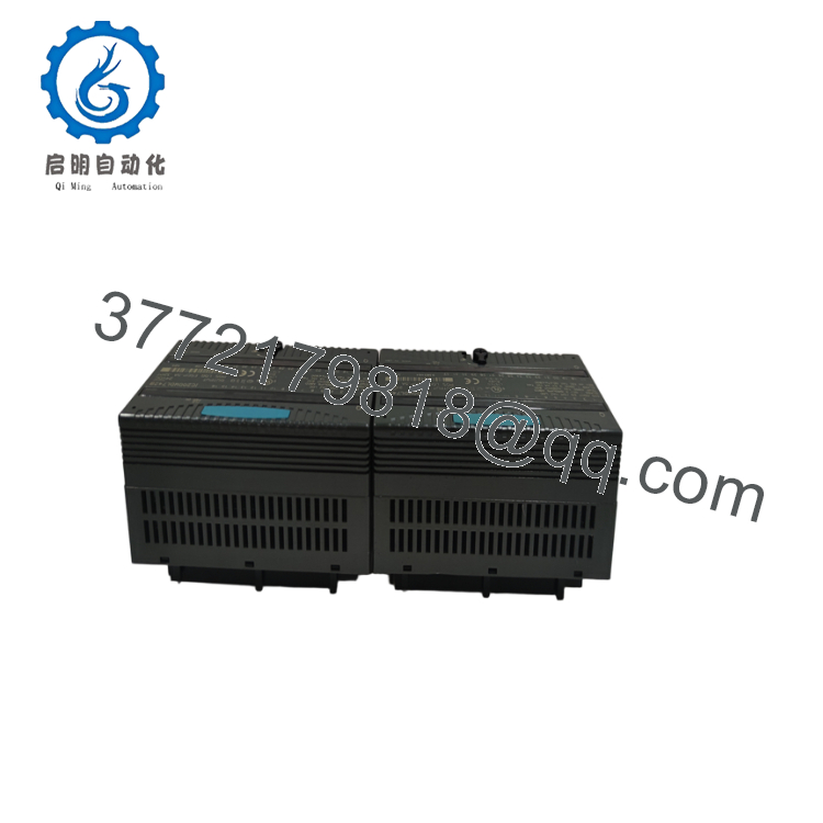
The GE IC200MDL742 is a 32-point discrete output module for the VersaMax PLC platform. It provides 32 positive-logic (sourcing) transistor outputs, organized into two isolated groups of 16 channels, making it ideal for controlling a large number of DC field devices from a compact PLC I/O station.
Each output includes Electronic Short Circuit Protection (ESCP) and electronic overcurrent protection. Individual amber LEDs indicate overloaded outputs, while green LEDs display output status. The module requires an external 24 VDC field power supply, while logic power is supplied through the VersaMax backplane.

- IC200MDL742
- IC200MDL742
5. Installation & Configuration Guide
Stage 1 – Pre-Installation Preparation (10 Minutes)
⚠️ Safety First
- Notify production personnel before shutdown.
- Perform Lock-Out/Tag-Out (LOTO).
- Remove power from the VersaMax station.
- Turn OFF the external 24 VDC field power supply.
- Wear an ESD wrist strap.
Required Tools
- Phillips screwdriver
- Digital multimeter
- ESD wrist strap
- Wire labels
- PLC wiring diagram
Backup Tasks
- Save the PLC project.
- Record output assignments.
- Photograph terminal wiring.
- Verify external field power wiring.
Stage 2 – Removing the Existing Module
- Switch OFF PLC and field power.
- Label all output wiring.
- Remove the terminal assembly.
- Release the locking latch.
- Pull the module straight from the carrier.
- Inspect the carrier connector for damage.
⚠️ Do not discard the original module until commissioning has been completed successfully.
Stage 3 – Installing the Replacement Module
- Verify the model number IC200MDL742.
- Install the module onto the VersaMax carrier.
- Lock the retaining latch.
- Reconnect all output wiring.
- Restore external 24 VDC field power.
- Verify output addressing in the PLC program.
Installation Checklist
- ✔ Correct module installed
- ✔ External field power connected
- ✔ Output wiring verified
- ✔ Module fully seated
- ✔ PLC configuration confirmed
Stage 4 – Startup & Functional Test
Before Applying Power
- Verify the external power supply is 18–30 VDC.
- Check wiring polarity.
- Confirm output loads are within rated current.
- Inspect for wiring shorts.
Startup Procedure
- Apply PLC backplane power.
- Apply external field power.
- Verify the OK LED and FLD PWR LED illuminate.
- Test each output individually.
- Confirm connected devices operate correctly.
- Verify no amber overload LEDs are illuminated.
⚠️ Troubleshooting
- FLD PWR LED OFF: Check the external 24 VDC power supply.
- Amber LED ON: Remove the overload or short circuit; the module automatically resumes normal operation once the fault is cleared.
- No output switching: Verify PLC logic and field wiring.
- Intermittent operation: Inspect grounding, wiring integrity, and output load current.
6. Frequently Asked Questions (FAQ)
Q1. How many outputs does the IC200MDL742 provide?
The module provides 32 discrete 24 VDC sourcing outputs, arranged in two groups of 16 outputs.
Q2. Does the module include short-circuit protection?
Yes. Every output channel features Electronic Short Circuit Protection (ESCP) and electronic overcurrent protection. If an overload occurs, the affected channel is indicated by an amber LED, and normal operation resumes after the fault is removed.
Q3. Does the IC200MDL742 require an external power supply?
Yes. The module requires an external 18–30 VDC (24 VDC nominal) field power supply for switching output loads. The module itself receives logic power from the VersaMax backplane.
Q4. What types of field devices can it control?
Typical applications include:
- Solenoid valves
- Relay coils
- Contactor coils
- Indicator lamps
- Alarm devices
- Small DC motors (through interposing relays)
- Industrial actuators
Q5. Is the IC200MDL742 still available?
The IC200MDL742 is a legacy VersaMax module. Although no longer in active production, New Surplus and professionally refurbished units remain available for maintaining existing automation systems.
Q6. What is the most common installation mistake?
The most common issue is forgetting to connect the external 24 VDC field power supply. Without field power, the PLC may recognize the module normally, but the outputs cannot energize connected loads.
Q7. What should be verified before returning the system to operation?
A commissioning engineer should confirm:
- Correct module model (IC200MDL742)
- External 24 VDC field power present
- Proper output wiring
- Output current within specification
- No overload or short-circuit indications
- Correct PLC output addressing
- Successful operation of all 32 outputs
- Stable VersaMax diagnostics
Completing these checks before restarting production helps ensure reliable digital output performance and minimizes unexpected downtime.



