
 WhatsApp: +86 16626708626
 Email:
  Phone: +86 16626708626
Description
3. Key Technical Specifications
| Parameter | Value |
|---|---|
| Model Number | IC200UEX626 |
| Manufacturer | GE Fanuc (Emerson) |
| Product Type | Analog Expansion Module |
| PLC Family | VersaMax Micro |
| Power Supply | 24 VDC (19.2–30 VDC operating) |
| Analog Inputs | 4 Channels |
| Analog Outputs | 2 Channels |
| Input Signal Types | 0–10 VDC, ±10 VDC, 0–20 mA, 4–20 mA |
| Output Signal Types | 0–10 VDC, 0–20 mA, 4–20 mA |
| Input Accuracy | ±1% Full Scale |
| Output Accuracy | ±1% Full Scale |
| Dimensions | 95 × 90 × 76 mm |
| Operating Temperature | 0°C to +55°C |
| Maximum Expansion | Up to 4 analog expansion modules per VersaMax Micro PLC (controller dependent) |
4. Product Introduction
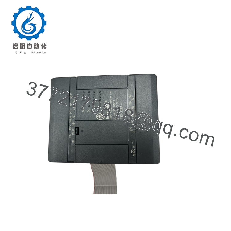
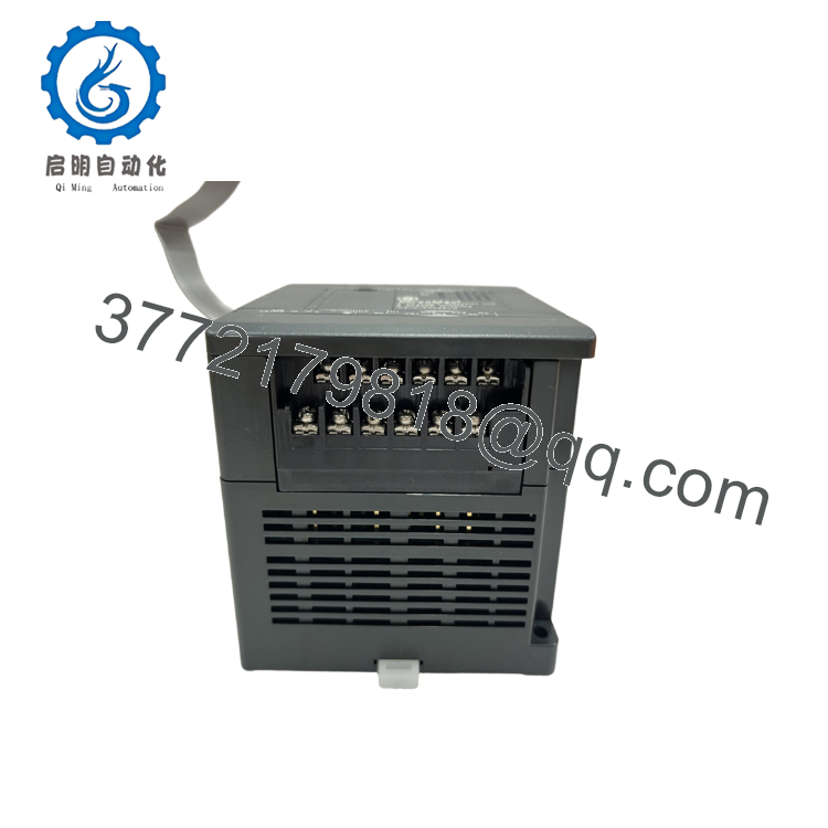
The GE IC200UEX626 is a 24 VDC-powered analog expansion module designed for the VersaMax Micro PLC family. It provides six analog channels, consisting of four configurable analog inputs and two configurable analog outputs, enabling the controller to interface with a wide range of industrial transmitters and actuators.
The analog inputs support 0–10 VDC, ±10 VDC, 0–20 mA, and 4–20 mA signals, while the outputs can generate 0–10 VDC, 0–20 mA, or 4–20 mA control signals. Typical applications include pressure, temperature, flow, and level measurement, as well as variable-speed drive control, valve positioning, and other process automation functions. A VersaMax Micro PLC can support multiple analog expansion units, allowing system capacity to grow with application requirements.

- IC200UEX626
- IC200UEX626
5. Installation & Configuration Guide
Stage 1 – Pre-Installation Preparation (10 Minutes)
⚠️ Safety First
- Notify operators before shutting down the PLC.
- Perform Lock-Out/Tag-Out (LOTO).
- Disconnect the 24 VDC supply.
- Verify all field wiring is de-energized.
- Wear an ESD wrist strap.
Required Tools
- Phillips screwdriver
- Digital multimeter
- ESD wrist strap
- Wire labels
- PLC programming software
Backup Tasks
- Save the PLC application.
- Record analog channel configuration.
- Photograph all terminal wiring.
- Document scaling parameters.
Stage 2 – Removing the Existing Module
- Turn OFF the PLC power.
- Label all analog wiring.
- Disconnect field terminals.
- Release the module latch.
- Remove the module carefully.
- Inspect connectors for damage.
⚠️ Retain the original module until commissioning has been completed successfully.
Stage 3 – Installing the Replacement Module
- Verify the model number IC200UEX626.
- Mount the module securely.
- Reconnect all analog wiring.
- Verify voltage/current jumper or configuration settings where applicable.
- Restore the PLC configuration.
- Confirm analog channel assignments.
Installation Checklist
- ✔ Correct model installed
- ✔ 24 VDC power available
- ✔ Analog wiring verified
- ✔ Configuration restored
- ✔ Expansion module recognized
Stage 4 – Startup & Functional Test
Before Applying Power
- Verify 24 VDC input power.
- Check analog signal wiring.
- Confirm proper grounding and shielding.
Startup Procedure
- Apply power.
- Verify the PLC recognizes the expansion module.
- Check each analog input using a calibrated signal source.
- Measure both analog outputs.
- Verify engineering-unit scaling.
- Confirm stable communication with the PLC CPU.
⚠️ Troubleshooting
- No analog readings: Verify the selected input type matches the connected transmitter.
- Output signal incorrect: Check output configuration and PLC scaling.
- Module not detected: Confirm the expansion cable and PLC compatibility.
- Noisy analog signals: Use shielded twisted-pair wiring and ground the shield at one end only.
6. Frequently Asked Questions (FAQ)
Q1. How many analog channels does the IC200UEX626 provide?
The module provides six analog channels consisting of four analog inputs and two analog outputs.
Q2. What signal types are supported?
The inputs support:
- 0–10 VDC
- ±10 VDC
- 0–20 mA
- 4–20 mA
The outputs support:
- 0–10 VDC
- 0–20 mA
- 4–20 mA
Q3. What power supply does the IC200UEX626 require?
The module operates from a 24 VDC power supply with an operating range of 19.2 to 30 VDC.
Q4. How many expansion modules can a VersaMax Micro PLC support?
Depending on the PLC model, a VersaMax Micro controller can support up to four analog expansion modules, allowing expansion to as many as 16 analog inputs and 8 analog outputs.
Q5. Is the IC200UEX626 still available?
Yes. Although it is a legacy VersaMax Micro product, New Surplus and professionally refurbished IC200UEX626 modules remain available to support existing automation systems.
Q6. What is the most common commissioning issue?
The most common issue is configuring the PLC for a different signal type than the connected field device. Always verify that voltage or current input/output settings match the transmitter or actuator before energizing the system.
Q7. What should be verified before returning the PLC to service?
A commissioning engineer should verify:
- Correct module model (IC200UEX626)
- Stable 24 VDC supply
- Proper analog input and output configuration
- Accurate signal scaling
- Correct wiring polarity
- PLC recognition of the expansion module
- Stable analog measurements
- Proper operation of all connected field devices
Completing these checks helps ensure accurate analog measurement and control while minimizing commissioning time and unexpected downtime.



