
 WhatsApp: +86 16626708626
 Email:
  Phone: +86 16626708626
Description
3. Key Technical Specifications
| Parameter | Value |
|---|---|
| Manufacturer | General Electric (GE) |
| Model Number | IC3600LIVD1 |
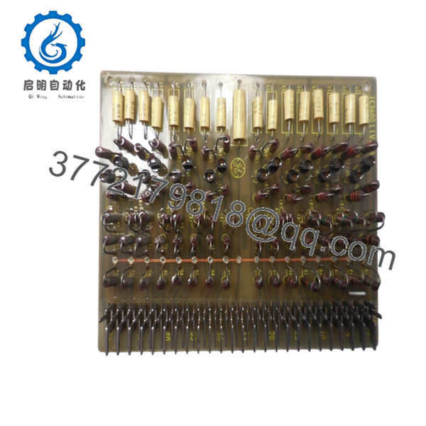
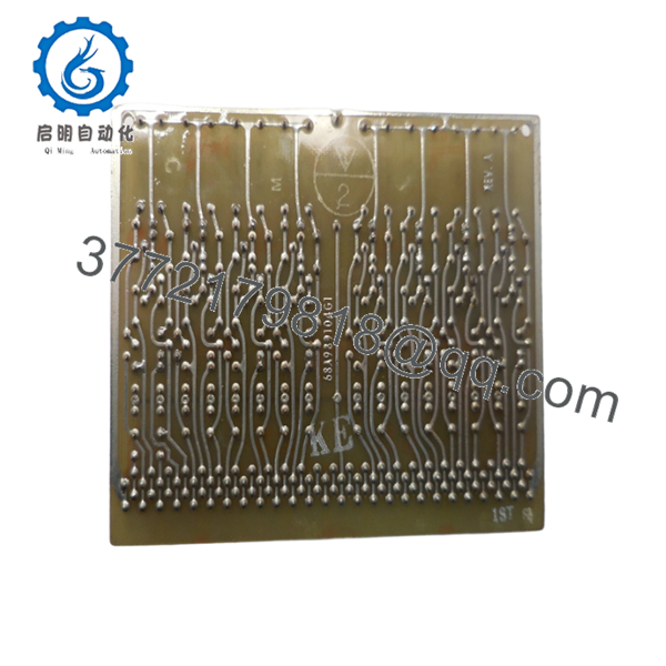
| Product Description | Logic Inverter Circuit Board |
| System Series | Mark I / Mark II IC3600 |
| Application | Speedtronic Gas & Steam Turbine Control |
| Interface | 51-pin edge connection |
| Board Function | Digital logic inversion processing |
| Circuit Components | 16 transistors, 17 capacitors, 80 resistors |
| Capacitor Rating | .001 µF ±10%, 200 V |
| Mounting Style | Rack-mounted PCB |
| Operating Environment | Industrial turbine control cabinet |
| Product Status | Legacy / Obsolete platform |
| Country of Original Manufacture | USA (historical production) |
| Condition Availability | New Surplus / Refurbished (tested) depending on stock |
The IC3600LIVD1 is a logic inverter card developed for GE Mark I and Mark II Speedtronic turbine control systems. GE released these systems in the early generations of Speedtronic architecture for gas and steam turbine management. Hundreds of these systems remain active in utilities, pipelines, and industrial power applications despite their age.
4. Product Introduction
GE IC3600LIVD1 is a Logic Inverter Circuit Board used within GE Mark I and Mark II Speedtronic turbine control systems. The board processes inverted digital logic signals required for turbine sequencing, shutdown logic, and protective functions in gas and steam turbine applications.
In field deployments of legacy Speedtronic systems, boards like IC3600LIVD1 remain in service because replacing an entire Mark II architecture often means major downtime and control migration costs. Plants typically stock spare boards specifically to avoid forced migration projects. Verify board revision and connector configuration before installation.
5. Installation & Configuration Guide
Stage 1: Pre-Installation Preparation (Estimated Time: 10 minutes)
⚠️ Safety First: Notify operations of downtime. Confirm turbine process safe state. Apply lockout/tagout. Disconnect cabinet power and wait at least 5 minutes for capacitor discharge.
Tools Required:
- ESD wrist strap
- PH1 screwdriver
- Fluke 115 multimeter
- Wire labels
- Smartphone for photos
- ESD work mat
Data Backup:
- Export existing turbine logic where applicable
- Record cabinet slot location
- Photograph wiring positions and board orientation
- Photograph jumper positions if present
- Document associated control card locations
I’ve watched techs assume “I’ll remember where that wire goes.” Two hours later they are tracing conductors with a flashlight.
Stage 2: Removing the Old Module (Estimated Time: 5 minutes)
- Remove cabinet cover or access panel.
- Label and disconnect all wiring.
- Remove retaining hardware.
- Pull board straight outward. Avoid twisting.
- Inspect edge connectors and backplane contacts.
⚠️ Note: Keep the old module beside the cabinet until startup succeeds. Legacy Mark systems often become troubleshooting references.
Stage 3: Installing the New Module (Estimated Time: 5–10 minutes)
- Connect ESD strap before touching board electronics.
- Verify exact model: IC3600LIVD1
- Configuration Clone (Crucial): Match all jumper settings and installation orientation from photos.
- Insert board evenly into slot guides.
- Secure retaining hardware.
- Reconnect wiring.
Self-Checklist:
- Model matches
- Wiring secured
- Connectors seated
- Jumpers verified
- Retention hardware tightened
❗This is the most common rookie mistake, but it happens constantly. Take a picture before you pull it. I can’t stress this enough.
Stage 4: Power-On & Testing (Estimated Time: 10 minutes)
Pre-Power Check
- Use multimeter to verify no short exists on supply rails
- Confirm cabinet grounding continuity
Power-up procedure:
- Energize control cabinet only
- Observe startup LEDs and cabinet diagnostics
- Confirm communication with associated modules
- Run dry I/O verification
- Observe turbine permissives and interlocks
⚠️ Troubleshooting Note: If logic faults appear after startup, suspect board revision mismatch or connector seating issues before replacing additional hardware.
I’ve seen technicians replace three boards before finding oxidation on a backplane contact.

- IC3600LIVD1
- IC3600LIVD1
6. Frequently Asked Questions (FAQ)
Q1: Can I hot-swap this module?
No. Do not hot-swap IC3600LIVD1. Mark I and Mark II systems were designed decades before modern hot-swap architectures became common. Pulling a live board risks damaging the backplane or creating unpredictable turbine control behavior.
Q2: Is IC3600LIVD1 obsolete, and is genuinely new stock still available?
Yes. This board belongs to a legacy Speedtronic generation and is obsolete. Some suppliers still provide New Surplus inventory and tested refurbished units. Availability changes frequently.
Q3: What replaces IC3600LIVD1 if stock runs out?
There is no simple drop-in migration path to newer Speedtronic generations. Mark IV, Mark V, and Mark VI platforms use different architecture and I/O strategies.
In real projects, replacement often becomes a broader migration discussion rather than a board swap.
Q4: Will I lose logic programming if I remove this board?
No. The IC3600LIVD1 itself performs logic inversion functions and is not the primary storage location for turbine application logic. Still, always back up system configuration before touching hardware.
Q5: Why are surplus units often cheaper than OEM pricing?
Because GE no longer manufactures many Mark II components. Secondary-market inventory comes from plant decommissioning, excess stock, and controlled surplus channels.
Lower price does not automatically mean counterfeit. It does mean inspection matters.
Q6: How do you verify board quality before shipment?
Our SOP follows practical field methods:
Inbound Inspection & Traceability
- Verify serial numbers and source documents
- Check for rework marks, corrosion, UV yellowing
- Inspect edge connectors and solder joints
- Audit accessories and labels
Live Functional Testing
- Install on a genuine GE test fixture
- Power-on sequence verification
- Communication checks
- Signal simulation testing
- Continuous load run >24 hours
Electrical Testing
- 500 V Megger insulation test (>10 MΩ)
- Ground continuity check
- Electrical parameter verification
Firmware & Configuration Verification
- Document hardware revision
- Photograph jumpers and configuration settings
Final QC
- QC sign-off
- ESD packaging
- Heavy-duty shipping carton
- QC label with test date
Test photos and videos are available upon request.
Q7: Any installation traps I should watch for?
Absolutely.
❗Firmware mismatch can create communication failures.
❗Connector orientation mistakes happen constantly.
❗Always calculate power loading with a 20% margin.
❗Use an ESD strap.
I once watched an engineer grab a board during winter with no wrist strap. Powered up the cabinet and immediately saw smoke. That’s an expensive lesson.
Keep these checks in mind and you’ll save yourself 90% of typical rework time.


