
 WhatsApp: +86 16626708626
 Email:
  Phone: +86 16626708626
Description
3. Key Technical Specifications
| Parameter | Value |
|---|---|
| Model Number | IC670ALG310 |
| Manufacturer | GE Fanuc (Emerson) |
| Product Type | Analog Voltage Output Module |
| Series | Field Control™ |
| Output Channels | 8 |
| Isolation | Two isolated groups of four channels |
| Output Ranges | 0 to 10 VDC, ±10 VDC (configurable) |
| Resolution | 14-bit |
| Output Overrange | Approximately ±10.25 V |
| External Output Power | 24 VDC required |
| Backplane Current Consumption | Approximately 170 mA |
| Calibration | Field recalibration supported; factory calibration stored in FLASH memory |
| Diagnostics | Overrange, underrange, module status, user power loss |
| Typical Applications | Process control, valve positioning, VFD speed reference, industrial analog control |
4. Product Introduction
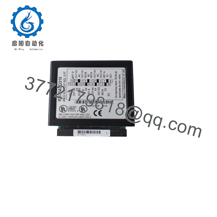
The GE IC670ALG310 is an 8-channel isolated analog voltage output module designed for the GE Field Control distributed I/O platform. It converts digital commands received from the Bus Interface Unit (BIU) into precision analog voltage outputs for industrial control devices such as variable frequency drives (VFDs), valve actuators, proportional controllers, and instrumentation.
The module provides eight independently configurable analog voltage outputs arranged in two electrically isolated groups of four channels. Each channel supports 0–10 VDC or ±10 VDC operation with 14-bit resolution, enabling accurate closed-loop process control. Calibration values are stored in onboard FLASH memory, and the module continuously performs diagnostics to detect output overrange, underrange, loss of user power, and calibration status.

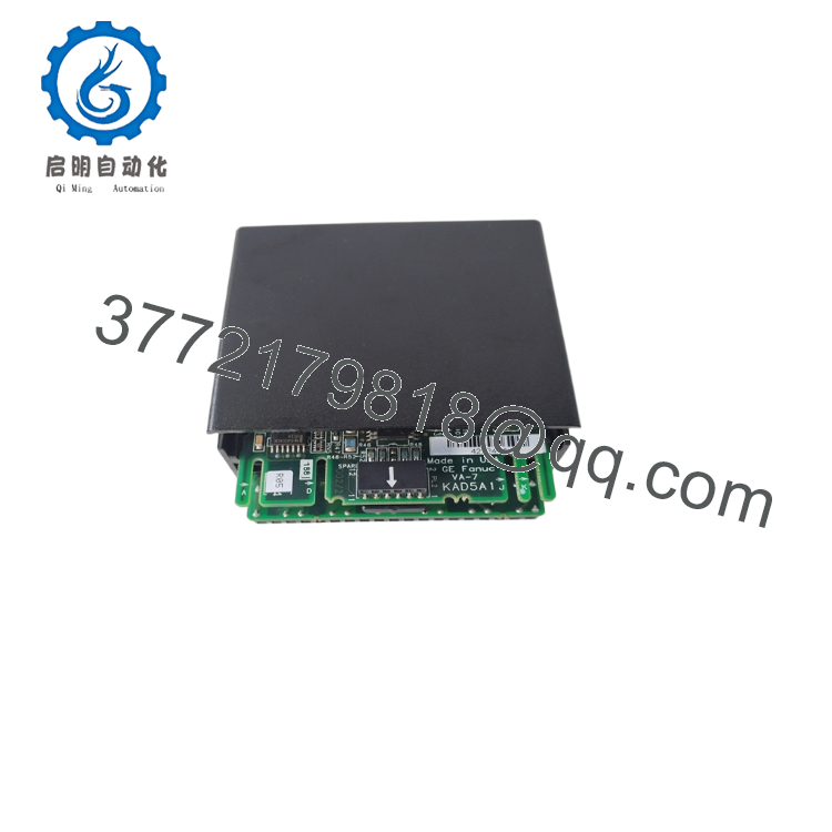
- IC670ALG310
- IC670ALG310
5. Installation & Configuration Guide
Stage 1 – Pre-Installation Preparation (10 Minutes)
⚠️ Safety First
- Notify operations before shutting down the Field Control station.
- Perform Lock-Out/Tag-Out (LOTO).
- Remove both backplane and external 24 VDC output power.
- Verify zero voltage before servicing.
- Wear an ESD wrist strap.
Required Tools
- Phillips screwdriver
- Digital multimeter
- Precision voltage meter
- ESD wrist strap
- PLC engineering software
Backup Tasks
- Save the controller configuration.
- Record channel scaling parameters.
- Photograph terminal wiring.
- Document analog output assignments.
Stage 2 – Removing the Existing Module
- Turn OFF system power.
- Label all field wiring.
- Disconnect the output terminals.
- Release the module from its base.
- Remove the module carefully.
- Inspect connectors and terminals for damage.
⚠️ Do not dispose of the original module until the replacement has passed commissioning.
Stage 3 – Installing the Replacement Module
- Verify the model number IC670ALG310.
- Install the module securely into the Field Control base.
- Connect the external 24 VDC output supply.
- Restore all field wiring.
- Configure the required voltage range for each channel.
- Download the PLC configuration if required.
Installation Checklist
- ✔ Correct module installed
- ✔ External 24 VDC connected
- ✔ Output ranges configured
- ✔ Wiring verified
- ✔ Module securely seated
Stage 4 – Startup & Functional Test
Before Applying Power
- Verify backplane power.
- Verify external 24 VDC supply.
- Check output wiring polarity.
Startup Procedure
- Apply system power.
- Verify the module status LED indicates normal operation.
- Confirm communication with the Bus Interface Unit.
- Test each analog output using a calibrated voltmeter.
- Verify engineering-unit scaling.
- Confirm proper operation of connected field devices.
⚠️ Troubleshooting
- Module LED flashing: Indicates a module fault; review controller diagnostics.
- No analog output: Verify external 24 VDC output power.
- Incorrect voltage: Check channel configuration and scaling parameters.
- Overrange/Underrange alarm: Verify configured output range and connected load.
6. Frequently Asked Questions (FAQ)
Q1. How many analog outputs does the IC670ALG310 provide?
The module provides 8 independent analog voltage outputs, arranged as two isolated groups of four channels.
Q2. Which output voltage ranges are supported?
Each channel can be configured for:
- 0 to 10 VDC
- ±10 VDC
The module also supports a small output overrange to approximately ±10.25 V for enhanced control performance.
Q3. What resolution does the module provide?
The IC670ALG310 uses 14-bit digital-to-analog conversion, providing high-resolution voltage output suitable for precision industrial control applications.
Q4. Does the module require an external power supply?
Yes. The analog output circuitry requires a separate 24 VDC external power supply in addition to the backplane power supplied by the Field Control system.
Q5. Can the module be recalibrated?
Yes. The IC670ALG310 supports field recalibration, and all calibration constants are stored in onboard FLASH memory, allowing recalibration without replacing hardware.
Q6. What diagnostic functions are available?
The module continuously monitors:
- Output overrange
- Output underrange
- Loss of external user power
- Calibration status
- General module health
These diagnostics help simplify troubleshooting and improve system reliability.
Q7. What should be verified before returning the system to service?
A commissioning engineer should confirm:
- Correct module (IC670ALG310)
- Stable backplane communication
- External 24 VDC supply present
- Proper output range configuration
- Accurate voltage output on all eight channels
- No diagnostic faults
- Successful communication with the Bus Interface Unit
- Correct operation of all connected field devices
Completing these checks helps ensure accurate analog output performance and reliable operation of the GE Field Control distributed I/O system.



