
 WhatsApp: +86 16626708626
 Email:
  Phone: +86 16626708626
Description
3. Key Technical Specifications
| Parameter | Value |
|---|---|
| Manufacturer | GE Fanuc (Emerson) |
| Model | IC687RCM711 |
| Product Type | Redundancy Communications Module (RCM) |
| Series | Series 90-70 |
| Primary Function | CPU synchronization and shared I/O transfer |
| Installation | Single-slot VME module for redundant rack |
| Backplane Supply | 5 VDC |
| Current Consumption | 1.2 A @ 5 V |
| Data Transfer Rate | 500 KB/s |
| Maximum Interconnecting Cable | 50 ft (15 m) |
| Communication | Non-isolated differential communication |
| Status Indicators | Five LEDs (BOARD OK, LOCAL READY, LOCAL ACTIVE, REMOTE READY, REMOTE ACTIVE) |
| Manual Switchover | Front-panel pushbutton |
| Typical Application | Hot Standby PLC redundancy systems |
The IC687RCM711 is designed specifically for GE Series 90-70 Hot Standby Redundancy systems. It transfers synchronization messages and shared I/O data between the active and backup CPUs to maintain continuous process operation during controller failover.
4. Product Introduction
The GE IC687RCM711 is a Redundancy Communications Module developed for the GE Fanuc Series 90-70 PLC platform. Installed in redundant controller racks, it provides the dedicated communication path required to synchronize the active and standby CPUs while continuously exchanging shared I/O data.
Plants operating power generation, water treatment, oil and gas, and continuous manufacturing systems commonly use this module because controller redundancy minimizes unplanned shutdowns. The manual switchover pushbutton, built-in diagnostic LEDs, and high-speed communication simplify maintenance while keeping the standby controller synchronized with the active system.

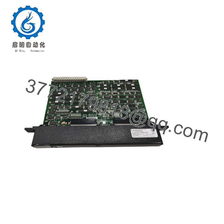
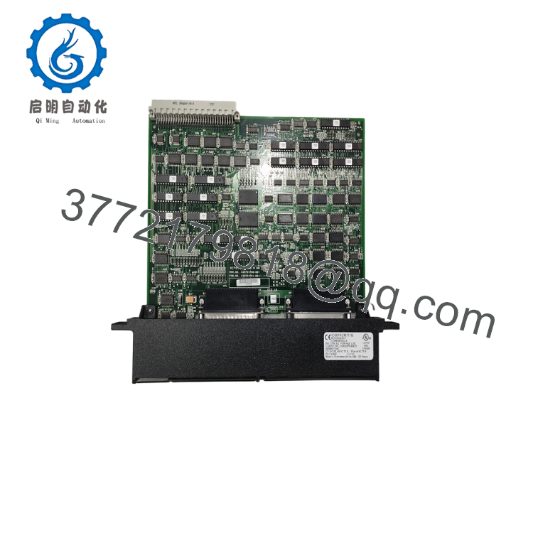
- IC687RCM711
- IC687RCM711
5. Installation & Configuration Guide
Stage 1 – Pre-Installation Preparation (10 Minutes)
⚠️ Safety First
- Notify operations before shutting down the redundant PLC.
- Perform Lock-Out/Tag-Out procedures.
- Remove power from both redundant racks.
- Wait at least five minutes before handling modules.
Tools Required
- ESD wrist strap
- PH1 screwdriver
- Digital multimeter
- Wire labels
- Smartphone for documentation
- GE Logicmaster or Windows programming software
Data Backup
- Save the PLC project.
- Record redundancy configuration.
- Photograph rack layout.
- Record firmware revisions.
- Document all communication settings.
Stage 2 – Removing the Existing Module (5 Minutes)
- Remove the module retaining screws.
- Disconnect the redundancy cable.
- Pull the module straight from the rack.
- Inspect connectors for bent pins or contamination.
- Leave the old module available until successful commissioning.
⚠️ Never force the module into or out of the VME backplane.
Stage 3 – Installing the Replacement Module (10 Minutes)
- Wear an ESD wrist strap.
- Confirm the replacement part number is IC687RCM711.
- Install the module into the designated redundant rack slot.
- Tighten retaining screws evenly.
- Connect the redundancy communication cable.
- Verify cable routing and connector seating.
Installation Checklist
- ✅ Correct module installed
- ✅ Connectors fully seated
- ✅ Retaining screws tightened
- ✅ Redundancy cable connected
- ✅ Rack inspection completed
Stage 4 – Power-On & Functional Testing (10 Minutes)
Before Applying Power
- Verify the 5 V backplane supply.
- Check for connector damage.
Commissioning
- Power both PLC racks.
- Observe all five status LEDs.
- Verify CPU synchronization.
- Confirm shared I/O updates correctly.
- Test manual switchover using the front-panel pushbutton.
- Return the redundant system to normal operation.
⚠️ Troubleshooting
- BOARD OK LED Off: Verify backplane power.
- LOCAL READY not illuminated: Check CPU configuration.
- REMOTE READY Off: Inspect redundancy cable.
- Synchronization failure: Confirm firmware compatibility and redundancy configuration.
6. Frequently Asked Questions (FAQ)
Q1. What does the IC687RCM711 actually do?
It provides the dedicated communication channel between the primary and standby CPUs in a Series 90-70 Hot Standby system. It continuously exchanges synchronization data and shared I/O information so the backup controller is ready to assume control if the active CPU fails.
Q2. Can this module be installed in a standard Series 90-70 PLC?
No. The IC687RCM711 is intended specifically for redundant rack configurations. Standard non-redundant systems use different hardware arrangements.
Q3. Is the IC687RCM711 still manufactured?
No. It is a legacy Series 90-70 product. Most available units today are New Surplus, refurbished, or professionally tested inventory.
Q4. Can I replace the module while power is on?
No. Although the redundant system minimizes downtime, replacing the RCM itself should be performed with power removed from the redundant rack. Hot replacement may interrupt synchronization and risk hardware damage.
Q5. Why is firmware matching important?
A redundancy pair must operate with compatible firmware and configuration. Mismatched revisions can prevent synchronization or cause the standby CPU to remain in a “Not Ready” state. Always document firmware before replacement.
Q6. What quality inspections should be performed before shipment?
A professional supplier should perform:
- OEM serial number verification
- Visual inspection for corrosion and repair marks
- Functional testing on a genuine Series 90-70 redundancy rack
- 24-hour operational verification
- Backplane power verification
- Communication and failover testing
- ESD-safe packaging
- QC inspection documentation
Requesting startup photos or a redundancy synchronization test video before shipment is recommended for legacy Hot Standby hardware.
Q7. What are the most common installation mistakes?
The most frequent issues are:
- Installing incompatible firmware revisions
- Connecting the redundancy cable incorrectly
- Mixing standard and redundant rack hardware
- Skipping manual failover testing after installation
- Removing the original module before verifying successful synchronization
Most commissioning delays can be avoided by documenting the original configuration before removing the existing module and verifying the standby CPU reaches the READY state after installation.



