
 WhatsApp: +86 16626708626
 Email:
  Phone: +86 16626708626
Description
Key Technical Specifications
| Parameter | Value |
| Processor Type | 80188EB running at 16 MHz |
| User Memory Capacity | 24 KB Fixed |
| Logic Execution Speed | 0.22 milliseconds per 1,000 words of boolean logic |
| Discrete I/O Capacity | Up to 1,024 inputs and 1,024 outputs (2,048 total) |
| Analog I/O Capacity | 256 inputs and 128 outputs |
| Maximum Baseplate Configurations | 4 total racks (1 CPU baseplate + up to 3 expansion racks) |
| Communication Support | SNP protocol via power supply port |
| Register Memory (%R) | 2,048 words fixed |
| Current Draw | 430 mA from +5 VDC backplane rail |
| Operating Temperature | 0 to +60 °C (32 to 140 °F) |
Product Introduction & Supply Chain Strategy
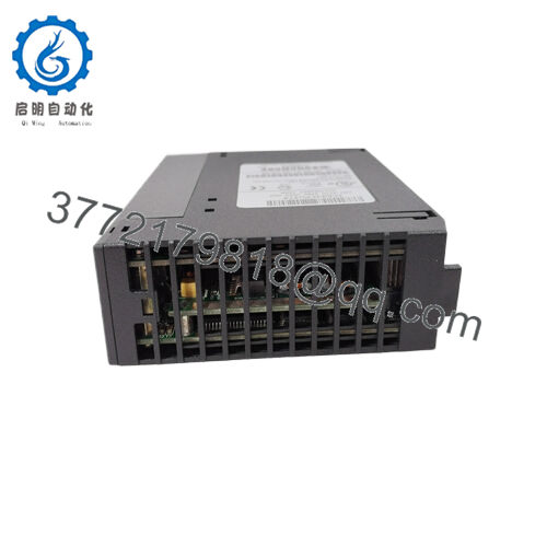
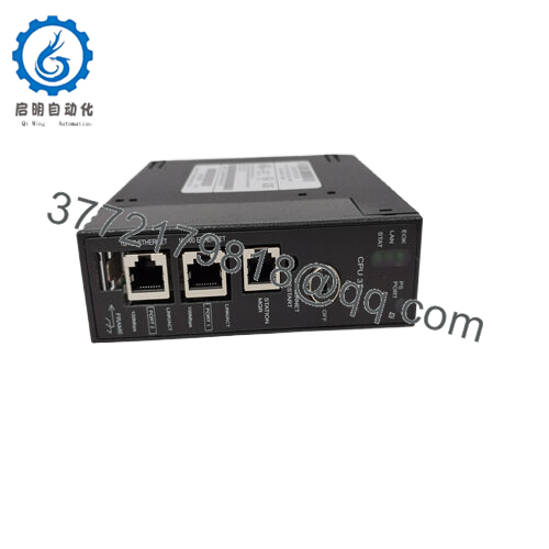
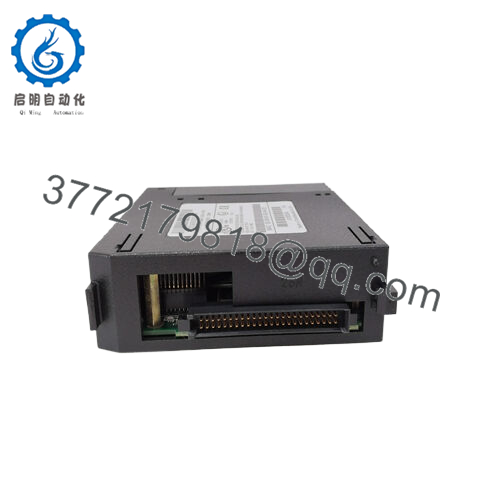
The GE Fanuc IC693CPU352-EK is a mid-range, baseplate-mounted central processing unit designed for the Series 90-30 PLC ecosystem. Operating at a clock speed of 16 MHz with a dedicated 24 KB user memory capacity, this processor is engineered to manage up to 2,048 discrete I/O points across a maximum of four racks. It delivers dependable, deterministic scan times for standard step-sequencing applications, small-scale packaging machinery, and localized material handling systems that rely on legacy serial network architectures.
From a supply chain continuity perspective, the IC693CPU352-EK represents a critical legacy asset. Because this model was officially discontinued by the OEM years ago, procurement teams face high lead time variability when sourcing reliable replacements. Selecting a verified Brand New Surplus module is the most cost-efficient method to protect your plant from long-term outages. Unlike used or refurbished alternatives—which frequently suffer from aged, brittle plastic casings and compromised internal logic gates—our new surplus inventory guarantees a zero-hour service history, providing a low Total Cost of Ownership (TCO) and full operational peace of mind.

- IC693CPU352-EK
Installation & Configuration Guide
Stage 1: Pre-Installation (Prep & Safety)
- Completely isolate and lock-out/tag-out (LOTO) all AC or DC input power sources connected to the PLC baseplate assembly.
- Put on an ESD-compliant grounded wrist strap, ensuring it makes direct skin contact, and attach the grounding clip to the unpainted steel panel frame.
- Archive the current logic configuration file from your backup server before physically interacting with the rack hardware.
Stage 2: Removal
- Loosen the top and bottom captive retaining screws located on the faceplate margins of the faulty CPU card.
- Firmly press down on the plastic ejection tabs on the upper and lower edges of the module housing.
- Slide the old CPU module horizontally straight out of the slot tracks. Do not shake or twist the card, as this can easily bend or shear the high-density backplane connector pins.
Stage 3: Installation (Clone & Seat)
- Unbox the new surplus IC693CPU363-EK module in your static-controlled zone and visually inspect the rear male pins for absolute alignment.
- Verify that the unit is being placed back into Slot 0 (the dedicated slot located on the far left of the baseplate, directly integrated next to the power supply bay).
- Push the module smoothly into the card guides until the rear pins seat completely into the backplane socket. Secure the top and bottom retaining screws to 6 in-lbs of torque.
Stage 4: Power-On & Testing
- Remove all LOTO safety devices and apply main input power to the system.
- Monitor the LED diagnostic panel on the front faceplate. The power supply PWR LED must light up solid green, followed shortly by the CPU OK indicator turning solid green after completing the power-on self-test.
- Connect your programming terminal running Logicmaster 90 or Proficy Machine Edition to the power supply serial port. Establish an online communication handshake.
- Download your archived application file, verify that the active software configurations align with the -EK revision parameters, and transition the controller into RUN mode.
Firmware/Software Versions & Upgrade Notes
The IC693CPU352-EK uses an integrated ROM chip containing its operating system firmware. As an older model within the Series 90-30 line, hardware version suffixes such as -EK denote specific manufacturing component revisions and specific embedded boot scripts.
When substituting older revisions (such as a legacy -AA or -CC version) with this updated -EK hardware, beware of software version constraints. Ensure your programming software configuration map lists the target device correctly as a CPU352. Forcing an incompatible, older memory allocation table onto the newer -EK module can throw an “invalid configuration” fault code on the master CPU status panel, preventing the logic engine from compiling or starting up until the profile configuration file is updated and downloaded again.
Frequently Asked Questions (FAQ)
What differentiates this New Surplus IC693CPU352-EK from refurbished units sold online?
This unit is a genuine New Surplus component. It has never spent an hour in an active control panel, has never run machine logic in a live production line, and features 100% original factory internals without any soldering repairs. Refurbished units are typically used items that have been cleaned up and have had degraded capacitors replaced; they carry a much higher risk of infant mortality or unexpected field failure.
Why is the CPU352 installed in Slot 0 instead of standard I/O slots?
The Series 90-30 system designates “Slot 0” as the dedicated position for the central processing unit, which is physically located on the left side of the baseplate adjacent to the power supply. Standard I/O modules cannot be inserted into this slot, and the CPU352 cannot be placed in slots 1 through 10, as those lack the necessary bus architecture lines to run the main logic processor.
Does this processor module support direct Ethernet connectivity?
No. The IC693CPU352-EK does not feature a built-in RJ-45 Ethernet port. Serial communication is achieved via the 15-pin D-shell connector located on the face of the adjacent power supply module using the SNP protocol. If Ethernet connectivity (SRTP or Modbus TCP) is required for your network layout, you must add an auxiliary IC693CMM321 Ethernet communications coprocessor module to the rack.
How does this CPU handle program retention during a power outage?
The module uses volatile RAM to maintain your active control program, timing registers, and system variables. To prevent memory loss when the main line power is switched off, the system depends entirely on the lithium backup battery located inside the power supply housing. We strongly suggest replacing this battery with a fresh cell every 12 to 24 months while the rack is powered to avoid program loss.
Is this legacy processor compatible with modern Windows-based programming software?
Yes. While this module was originally programmed using legacy DOS-based Logicmaster 90 software, it is fully compatible with modern Windows-based configuration software, including Proficy Machine Edition (PME). You simply select the Series 90-30 option and choose the CPU352 model from the hardware catalog tree when building your project configuration file.



