
 WhatsApp: +86 16626708626
 Email:
  Phone: +86 16626708626
Description
3. Key Technical Specifications
| Parameter | Value |
|---|---|
| Manufacturer | GE Fanuc / Emerson |
| Model | IC697CMM742 |
| Product Series | Series 90-70 |
| Product Type | Type 2 Ethernet Interface Module |
| Installation | Single slot in Series 90-70 CPU rack |
| Ethernet Interfaces | 10BaseT (RJ45), 10Base2 (BNC), AUI (15-pin) |
| Ethernet Speed | 10 Mbps IEEE 802.3 CSMA/CD |
| Serial Ports | RS-232 Station Manager, RS-485 Software Load |
| Supported Protocols | SRTP, SNP/SNPX, CCM, Ethernet Global Data (EGD)* |
| LED Indicators | MODULE OK, LAN ONLINE, SERIAL ACTIVE, STATUS |
| Power Consumption | 2.0 A @ +5 VDC, 0.5 A @ +12 VDC (maximum with AUI transceiver) |
| Internal Protection | 5 × 20 mm, 250 V, 1.0 A slow-blow fuse |
| Operating Temperature | 0 °C to +55 °C |
| Maximum Modules | Up to four IC697CMM742 modules per CPU rack |
*EGD support depends on CPU firmware revision and module firmware level.
4. Product Introduction
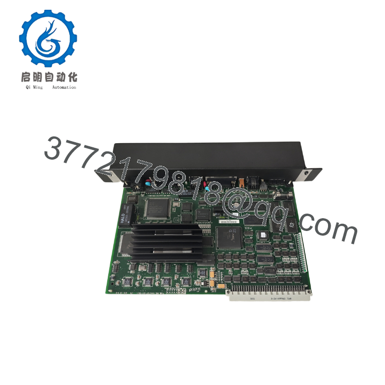
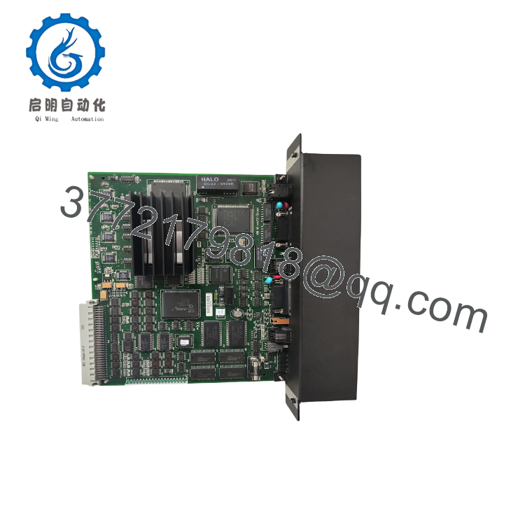
The GE IC697CMM742 is a Type 2 Ethernet Interface Module developed for the Series 90-70 PLC platform. It provides Ethernet connectivity between the PLC and supervisory systems, engineering workstations, HMIs, historians, and peer controllers. The module occupies one slot in the CPU rack and supports multiple physical Ethernet media, making it suitable for both legacy and transitional industrial networks.
Unlike modern integrated Ethernet CPUs, the IC697CMM742 adds network capability through a dedicated communications processor. It supports Station Manager diagnostics, firmware loading, and industrial Ethernet messaging while maintaining compatibility with many existing Series 90-70 installations. Before replacement, verify both CPU firmware and Ethernet module firmware because some network functions require minimum firmware revisions.

- IC697CMM742
- IC697CMM742
5. Installation & Configuration Guide
Stage 1 – Pre-Installation Preparation (10 Minutes)
⚠️ Safety First
- Notify operations personnel of the scheduled outage.
- Bring the controlled equipment to a safe operating condition.
- Apply Lockout/Tagout procedures.
- Remove power from the PLC rack.
- Wait at least 5 minutes before handling electronic modules.
Tools Required
- Grounded ESD wrist strap
- PH1 screwdriver
- Fluke 115 digital multimeter
- Ethernet cable tester
- Laptop with Proficy Machine Edition or Logicmaster software
- Smartphone for documentation
Data Backup
Before removing the module:
- Save the PLC hardware configuration.
- Record the module IP address.
- Document subnet mask and gateway.
- Record CPU firmware revision.
- Photograph all communication cables.
- Record network topology.
Stage 2 – Removing the Existing Module (5 Minutes)
- Disconnect rack power.
- Disconnect Ethernet and serial cables.
- Label every cable before removal.
- Release the retaining latch.
- Pull the module straight from the rack.
Inspect for:
- Bent backplane connectors
- Damaged RJ45 or BNC connectors
- Corrosion
- Dust accumulation
- Heat discoloration
⚠️ Keep the original module until the replacement has completed network commissioning.
Stage 3 – Installing the New Module (10 Minutes)
- Wear a grounded ESD wrist strap.
- Verify the catalog number:
IC697CMM742
- Install the module into the designated rack slot.
- Ensure the connector is fully seated.
- Secure the retaining mechanism.
- Reconnect all communication cables.
- Verify Ethernet media selection matches the installed network.
Installation Checklist
- Correct model installed
- Module fully seated
- Network cables identified
- Shield grounding verified
- Status LEDs operational
Stage 4 – Power-On & Communication Testing (15–20 Minutes)
Pre-Power Checks
- Verify rack power supply voltage.
- Check Ethernet cable continuity.
- Confirm IP address assignment.
- Verify no duplicate network addresses.
Startup Procedure
- Energize the PLC rack.
- Observe:
- MODULE OK
- LAN ONLINE
- SERIAL ACTIVE
- STATUS
- Connect through Station Manager or engineering software.
- Confirm:
- Module recognition
- Ethernet connectivity
- PLC communication
- HMI/SCADA communication
- Test data exchange with supervisory systems.
⚠️ Troubleshooting
If the LAN ONLINE LED remains off:
- Verify Ethernet cable type.
- Confirm switch port configuration.
- Check IP address conflicts.
- Verify firmware compatibility.
- Test the network using the Station Manager diagnostic port.
SOP Quality Verification
Every production-critical IC697CMM742 should undergo a documented inspection before shipment:
Inbound Inspection & Traceability
- Verify OEM labels and serial numbers.
- Inspect for rework marks, corrosion, connector wear, or UV discoloration.
- Confirm part number and hardware revision.
- Verify included accessories where applicable.
Live Functional Testing
Testing should be completed on a genuine Series 90-70 PLC rack.
The verification process includes:
- Power-on self-test
- LED verification
- Ethernet communication testing
- RS-232 Station Manager communication
- RS-485 software load port verification
- Continuous operation for more than 24 hours
- Generation of a documented functional test report
Test photographs and communication videos should be available upon request.
Electrical Verification
- Insulation resistance test using a 500 V Megger (>10 MΩ)
- Ground continuity verification
- Power rail measurements
Firmware Verification
- Record installed firmware revision.
- Verify compatibility with the customer’s CPU firmware.
- Document any hardware revision suffix.
Final QC
- QC inspector sign-off
- Anti-static ESD packaging
- Bubble-wrap protection
- Heavy-duty corrugated carton
- QC Passed label with inspection date
Technical Pitfalls & Survival Guide
❗ Firmware Compatibility
I’ve seen replacement projects delayed for two days because the Ethernet module firmware supported features the CPU firmware did not.
Before ordering, document both the CPU firmware and the Ethernet module firmware. Certain Ethernet Global Data (EGD) functions require CPU firmware Release 6.00 or later and compatible IC697CMM742 firmware.
❗ Ethernet Media Selection
The IC697CMM742 provides three physical Ethernet interfaces:
- 10BaseT
- 10Base2
- AUI
Only connect the interface appropriate for your network design. I’ve encountered installations where technicians mistakenly connected both 10BaseT and 10Base2 during troubleshooting, creating unnecessary confusion.
❗ Legacy Network Infrastructure
Many Series 90-70 systems still use hubs or coaxial Ethernet segments.
Don’t assume the plant has migrated entirely to switched RJ45 Ethernet. Verify the physical network before replacing the module.
❗ Power Supply Capacity
This module draws approximately 2.0 A from the 5 V backplane.
In a rack populated with several communication modules, available backplane power can become a limiting factor. Recalculate rack loading after hardware changes.
❗ Electrostatic Discharge (ESD)
Communication ASICs are sensitive to static electricity.
I’ve watched a replacement Ethernet module fail immediately after installation because it was handled without a grounded wrist strap during dry winter conditions.
Keep these checks in mind and you’ll avoid most of the communication problems that extend plant downtime.
6. Frequently Asked Questions (FAQ)
Q1. What does the IC697CMM742 do?
The IC697CMM742 provides Ethernet communication for GE Series 90-70 PLCs. It enables programming, diagnostics, PLC-to-PLC communication, HMI connectivity, and integration with SCADA systems over industrial Ethernet.
Q2. Can I hot-swap the IC697CMM742?
No.
The module is not designed for hot replacement. Shut down the PLC rack before removing or installing the module to prevent backplane damage or communication faults.
Q3. Which Ethernet interfaces are available?
The module includes:
- One 10BaseT RJ45 port
- One 10Base2 BNC port
- One AUI (15-pin) interface
- One RS-232 Station Manager port
- One RS-485 Software Load port
This flexibility makes it suitable for many legacy Ethernet installations.
Q4. Is the IC697CMM742 obsolete?
Yes.
The Series 90-70 platform is a legacy GE PLC family. New Original inventory is increasingly limited, while New Surplus and professionally tested refurbished modules remain available for maintaining installed systems. Long-term maintenance plans should account for future availability.
Q5. Why won’t my Ethernet network communicate after replacement?
The most common causes are:
- Incorrect IP address
- Firmware incompatibility
- Unsupported CPU firmware revision
- Incorrect Ethernet media selection
- Faulty network cabling
In my experience, configuration mismatches are much more common than hardware failures.
Q6. What inspections should I request before shipment?
For production-critical installations, request:
- OEM serial number verification
- Visual inspection for corrosion or connector damage
- Functional testing on a genuine Series 90-70 rack
- Ethernet communication verification
- RS-232 and RS-485 port testing
- Continuous 24-hour burn-in
- Firmware revision documentation
- ESD-safe packaging
- QC inspection report
These records help reduce commissioning risk and provide traceability for legacy control systems.



