
 WhatsApp: +86 16626708626
 Email:
  Phone: +86 16626708626
Description
3. Key Technical Specifications
| Parameter | Value |
|---|---|
| Manufacturer | GE Fanuc / Emerson |
| Model | IC697MDL653 |
| Product Series | Series 90-70 |
| Product Type | 24 VDC Discrete Input Module |
| Input Channels | 32 |
| Group Configuration | 4 isolated groups of 8 inputs |
| Rated Input Voltage | 24 VDC |
| Input Voltage Range | -3 to +30 VDC |
| Input Current | 10 mA per channel (typical) |
| Input Impedance | 2.6 kΩ (typical) |
| ON-State Voltage | 13.5 to 30 VDC |
| OFF-State Voltage | 0 to 5 VDC |
| Input Filter | 1 ms or 10 ms selectable |
| Isolation | 1,500 V input-to-backplane; 500 V between groups |
| Backplane Current | 300 mA @ 5 VDC |
| Interrupt Capability | First input configurable as interrupt |
| Wiring Compatibility | Positive Logic / Negative Logic |
| Compatible Devices | Dry contacts, proximity switches, electronic sensors |
| Installation | Series 90-70 VME rack |
4. Product Introduction
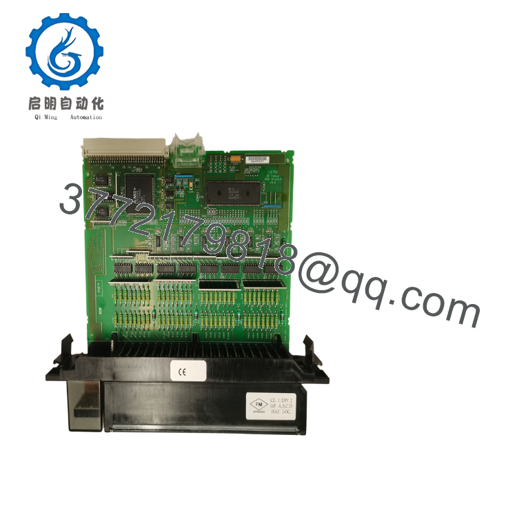
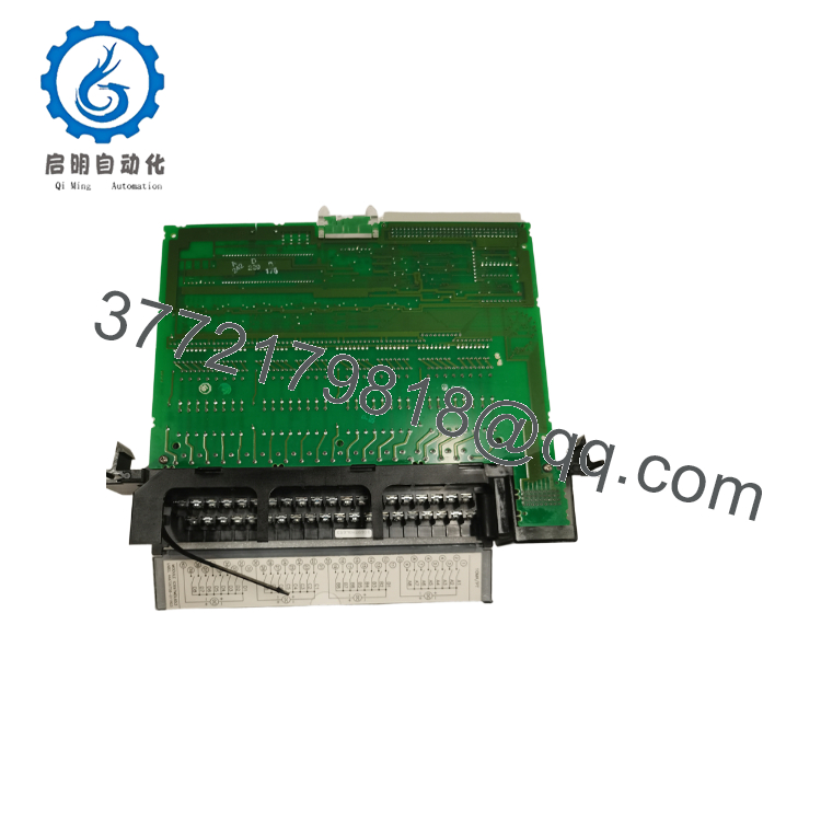
The GE IC697MDL653 is a 32-point 24 VDC digital input module for the Series 90-70 PLC platform. It acquires discrete field signals from pushbuttons, limit switches, proximity sensors, relay contacts, and other industrial devices. The module divides its inputs into four electrically isolated groups to improve noise immunity and simplify field wiring.
The module supports both positive and negative logic wiring, making it suitable for legacy control systems that use different field wiring standards. Configurable 1 ms or 10 ms input filtering allows engineers to balance response time against electrical noise, while the first input channel can be configured as a hardware interrupt for time-critical applications.

- IC697MDL653
- IC697MDL653
5. Installation & Configuration Guide
Stage 1 – Pre-Installation Preparation (10 Minutes)
⚠️ Safety First
- Notify operations of the scheduled shutdown.
- Bring the controlled equipment to a safe operating condition.
- Apply Lockout/Tagout (LOTO).
- Remove power from the PLC rack.
- Wait at least 5 minutes before handling electronic modules.
Tools Required
- Grounded ESD wrist strap
- PH1 screwdriver
- Fluke 115 digital multimeter
- Wire labels
- Smartphone for documentation
- Programming laptop
Data Backup
Before replacing the module:
- Save the PLC hardware configuration.
- Record slot assignment.
- Photograph all field wiring.
- Label every cable.
- Record any configured interrupt input.
Stage 2 – Removing the Existing Module (5 Minutes)
- Verify rack power is OFF.
- Remove the front terminal connector.
- Label all field wiring.
- Release the retaining mechanism.
- Pull the module straight from the rack.
Inspect:
- Backplane connector
- Terminal connector
- Signs of overheating
- Dust accumulation
- Bent connector pins
⚠️ Keep the original module until every input channel has been verified.
Stage 3 – Installing the New Module (10 Minutes)
- Wear a grounded ESD wrist strap.
- Verify the replacement catalog number:
IC697MDL653
- Insert the module completely into the Series 90-70 rack.
- Lock the retaining mechanism.
- Reconnect the field wiring.
- Confirm wiring polarity matches the original installation.
Installation Checklist
- Correct model installed
- Module fully seated
- Terminal connector secured
- Wiring verified
- Grounding confirmed
Stage 4 – Power-On & Functional Testing (15 Minutes)
Pre-Power Checks
- Verify 24 VDC field supply.
- Check for wiring shorts.
- Confirm field commons.
- Verify backplane power.
Startup Procedure
- Energize the PLC rack.
- Observe module LEDs.
- Verify the CPU recognizes the module.
- Test every input point individually.
- Confirm all field devices report correctly in the PLC software.
⚠️ Troubleshooting
If input LEDs do not respond:
- Verify field voltage is within specification.
- Check positive/negative logic wiring.
- Confirm input filter settings.
- Inspect the field common wiring.
- Verify the terminal connector is fully seated.
SOP Quality Verification
Every production-critical IC697MDL653 should be inspected before shipment.
1. Inbound Inspection & Traceability
- Verify OEM labels and serial numbers.
- Inspect for corrosion, scratches, rework marks, and connector wear.
- Confirm hardware revision.
- Review available traceability records.
2. Live Functional Testing
Testing should be performed on a genuine Series 90-70 PLC rack.
Verification includes:
- Power-on self-test
- LED functionality
- 32-channel input simulation
- Positive and negative logic verification
- 1 ms and 10 ms filter testing
- Continuous operation exceeding 24 hours
- Generation of a documented functional test report
Test photographs and videos should be available upon request.
3. Electrical Verification
- 500 V insulation resistance test (>10 MΩ)
- Ground continuity check
- Backplane current verification
4. Configuration Verification
- Record hardware revision.
- Verify interrupt input operation if required.
- Document module identification.
5. Final QC
- QC inspector approval
- ESD-safe packaging
- Bubble-wrap protection
- Heavy-duty corrugated carton
- QC Passed label with inspection date
Technical Pitfalls & Survival Guide
❗ Positive vs. Negative Logic
This is the mistake I encounter most often.
I’ve seen technicians replace the hardware only to discover every input appears permanently ON because the field wiring uses negative logic while the replacement was wired assuming positive logic. Before disconnecting the original module, document the wiring scheme carefully.
❗ Input Filter Settings
The module supports 1 ms and 10 ms input filtering.
If you’re monitoring fast sensors, a 10 ms filter can mask short pulses. On the other hand, using a 1 ms filter in a noisy electrical cabinet may result in nuisance transitions. Choose the filter based on the application rather than leaving the default setting.
❗ Group Isolation
Each group of eight inputs is electrically isolated.
Don’t assume all commons are interchangeable. Mixing commons between isolated groups can produce difficult-to-diagnose intermittent faults, especially after panel modifications.
❗ Proximity Sensor Compatibility
The IC697MDL653 is compatible with standard 24 VDC proximity switches, but verify the sensor’s output current and wiring type (PNP/NPN) before installation. A mismatch can prevent reliable input detection even though the module itself is functioning normally.
❗ Electrostatic Discharge (ESD)
I’ve watched a maintenance technician remove a Series 90-70 input module during winter without wearing a grounded wrist strap. The replacement appeared normal initially, but several channels became unreliable after commissioning.
Always use a grounded wrist strap and work on an ESD-safe surface.
Keep these checks in mind and you’ll avoid most of the rework that extends maintenance outages.
6. Frequently Asked Questions (FAQ)
Q1. What does the IC697MDL653 do?
The IC697MDL653 receives 32 discrete 24 VDC field input signals and transfers their status to a GE Series 90-70 PLC. It supports both positive and negative logic wiring and is compatible with dry contacts, proximity switches, and electronic sensors.
Q2. Can the IC697MDL653 be hot-swapped?
No.
The Series 90-70 platform does not support hot replacement of this module. Shut down the PLC rack and follow Lockout/Tagout procedures before removing or installing the module.
Q3. Is the IC697MDL653 obsolete?
Yes.
The module has been discontinued as part of the legacy Series 90-70 product family. New Original inventory is limited, while New Surplus and professionally tested refurbished units remain available through industrial spare-parts suppliers.
Q4. Which field devices can connect to this module?
Typical devices include:
- Mechanical limit switches
- Pushbuttons
- Selector switches
- Inductive proximity sensors
- Photoelectric sensors
- Relay contacts
- 24 VDC electronic outputs
The module is designed to accept 24 VDC discrete signals within the specified voltage range.
Q5. Why are there four isolated input groups?
Electrical isolation improves noise immunity and allows separate field power distribution. It also limits the impact of faults to a single group rather than affecting all 32 channels. This architecture is particularly useful in large industrial panels with multiple field power sources.
Q6. What inspections should I request before shipment?
For production-critical applications, request:
- OEM serial number verification
- Visual inspection for connector wear and corrosion
- Functional testing of all 32 input channels
- Verification of both positive and negative logic operation
- 24-hour operational burn-in
- 500 V insulation resistance test
- Hardware revision documentation
- ESD-safe packaging with QC records
Requesting test photographs and channel verification reports before shipment can significantly reduce commissioning risk for legacy Series 90-70 systems.



