
 WhatsApp: +86 16626708626
 Email:
  Phone: +86 16626708626
Description
Key Technical Specifications
- Model: IC698CPE030-GJ
- Manufacturer: GE Fanuc / GE Intelligent Platforms
- Platform: PACSystems RX7i
- Processor: 600 MHz Pentium-M
- User Memory: 64 MB battery-backed memory
- User Flash: 64 MB nonvolatile flash memory
- Backplane Interface: VME64
- Ethernet: Two auto-sensing 10/100 Mbps RJ-45 ports
- Serial Ports: Three isolated ports — RS-232, RS-485, and RS-232 Ethernet Station Manager
- Serial Protocols: SNP, Modbus RTU Slave, and serial I/O
- Supported System Modules: RX7i modules, Series 90-70 discrete and analog I/O, VME modules, and compatible communications modules
- Battery: IC698ACC701 lithium battery pack
- Operating Temperature: 0 to 60 °C
- Storage Temperature: −40 to 85 °C
- Firmware Reference: GJ revision commonly listed with CPU firmware 6.01 and Ethernet firmware 6.00; verify the installed revision before deployment
- Backplane Current: Approximately 3.4 to 3.6 A at 5 VDC; use the exact hardware-revision datasheet for rack power calculations
Product Introduction
The GE Fanuc IC698CPE030-GJ is a PACSystems RX7i CPU processor module for real-time control in VME64-based PLC systems. It executes control logic and exchanges data through two embedded 10/100 Mbps Ethernet ports, three isolated serial ports, and the RX7i backplane.
The module provides a 600 MHz Pentium-M processor, 64 MB user memory, and 64 MB nonvolatile flash memory. It remains useful for maintaining installed RX7i and Series 90-70 systems, but firmware, battery condition, rack loading, and exact hardware revision must be checked before replacement.
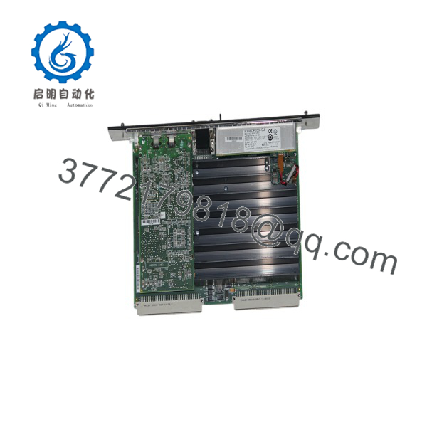
IC698CPE030-GJ
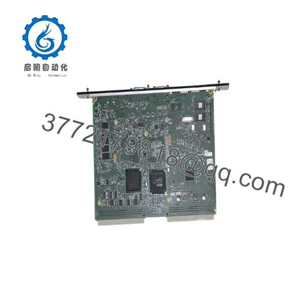
IC698CPE030-GJ
Installation & Configuration Guide
Stage 1: Pre-Installation Preparation — 5 to 10 Minutes
⚠️ Safety First: Notify operations, place the process in a verified safe state, and complete lockout/tagout before removing the CPU. Wait at least 5 minutes for capacitor discharge, then confirm the rack is de-energized with a properly rated multimeter.
Tools Required:
- ESD wrist strap and grounded ESD mat
- PH1 screwdriver
- Calibrated multimeter
- Wire labels and marker
- Smartphone or camera for configuration photos
- Correct programming cable and PACSystems programming software
Data Backup:
- Export the running logic, hardware configuration, and reference data.
- Record the CPU IP address, subnet mask, gateway, SNP settings, and Ethernet Global Data configuration.
- Record the installed CPU and Ethernet firmware versions.
- Photograph the CPU faceplate, serial connectors, Ethernet connections, rack position, and terminal wiring.
- Photograph any DIP switches or jumpers if they are present on associated communication or I/O modules. The IC698CPE030 CPU itself does not use a conventional field node-address DIP arrangement.
Stage 2: Removing the Old Module — 5 Minutes
- Remove the front bezel or protective cover without pulling on Ethernet or serial cables.
- Label each cable, then disconnect it without forcing the connector.
- Release the rack locking tabs or retaining screws.
- Pull the CPU straight out to avoid damaging VME backplane pins.
- Inspect the backplane connector for bent pins, contamination, or loose hardware.
- Keep the old CPU beside the rack until the replacement has completed commissioning.
Stage 3: Installing the New Module — 5 to 10 Minutes
- Put on the grounded ESD wrist strap and verify the replacement label reads IC698CPE030-GJ.
- Compare the replacement hardware revision, serial number, firmware label, and connector arrangement with the removed unit.
- Clone all documented configuration settings. For associated modules, mirror DIP switches and jumpers exactly, including termination and communication settings.
- Slide the CPU into the correct RX7i rack slot. Keep it square with the guide rails.
- Press firmly until the retaining mechanism engages. Do not use the front connectors as a handle.
- Reconnect Ethernet and serial cables according to the photographs and labels.
- Tighten retaining screws or locking tabs. Use the connector manufacturer’s torque specification rather than guessing.
Self-Checklist:
- Exact model and hardware revision verified
- [] Firmware documented
- [] IP and serial settings recorded
- [] DIP switches and jumpers cloned where applicable
- [] Cables returned to the correct ports
- [] CPU fully seated
- [] Retaining tabs or screws secured
Stage 4: Power-On and Testing — 10 to 15 Minutes
- Use the multimeter to check the rack’s 5 VDC supply and verify there is no short on the power rail.
- Power up the rack only. Keep field devices inhibited during initial testing.
- Observe the CPU LEDs through the complete boot sequence. A completed startup should produce the expected OK status; a persistent fault indication requires diagnosis before proceeding.
- Connect the programming software and verify the CPU identity, IP configuration, firmware version, and hardware configuration.
- Download the backed-up logic only if the replacement does not retain the required application and configuration.
- Confirm Ethernet communications with the HMI, supervisory system, and required PACSystems devices.
- Test serial devices using the applicable SNP or Modbus RTU settings.
- Perform a dry-run I/O test with outputs inhibited, then test inputs and outputs under an approved operating procedure.
- Return the process to service only after the CPU, communications, diagnostics, and sequence logic have passed the site acceptance checklist.
⚠️ Troubleshooting Note: A solid fault indication can result from incompatible firmware, invalid hardware configuration, or a battery-related memory problem. If Ethernet communication fails, check the IP address, subnet, cable, switch port, and duplicate-IP condition before changing the program.
Frequently Asked Questions (FAQ)
Can I hot-swap the IC698CPE030-GJ under power?
Do not assume that this CPU can be hot-swapped. The RX7i CPU connects directly to the VME64 backplane, and removing it under power can interrupt the controller and damage connectors or create an uncontrolled process state. Shut down the rack, complete lockout/tagout, and confirm the site procedure before removal.
Is the IC698CPE030-GJ obsolete?
The -GJ is a legacy RX7i hardware revision. It may still be available as new surplus, used, or refurbished stock, but condition varies by supplier. Request photographs of the nameplate, serial number, firmware screen, and test report; do not treat “new” as equivalent to factory-sealed without evidence.
What is the direct replacement if this model is unavailable?
There is no universal drop-in replacement based only on the base number. Later revisions, including -JP variants, may require firmware, hardware, battery, application, or system compatibility checks. A migration to another RX7i CPU or newer PACSystems platform should be engineered against the rack, firmware, communications, and application requirements.
Will I lose the PLC program when I remove the old CPU?
The program may remain in nonvolatile flash, but you should not rely on that during a replacement. Battery-backed memory can lose data if the battery is weak or disconnected, so export the logic and hardware configuration before shutdown. Check the installed IC698ACC701 battery condition and replace it according to the OEM procedure if its status is uncertain.
Does the GJ suffix affect compatibility?
Yes. The suffix identifies a hardware revision and should be matched against the installed firmware and application requirements. Published documentation associates -GJ with CPU firmware 6.01 and Ethernet firmware 6.00, but the actual module may have been updated; verify the revision online before installation.
Why is the price lower than the OEM list price?
Legacy automation modules are often sourced from surplus inventory, plant closures, discontinued-stock brokers, or tested exchange inventory. The lower price does not prove equivalence to factory-sealed stock. Confirm whether the unit is New Original / New Surplus, used, or refurbished, and obtain the warranty period, test report, serial-number photographs, and return terms in writing.
What testing should the supplier provide?
Ask for a documented power-on test, LED and boot-sequence verification, Ethernet communication test, serial-port test, firmware readout, and battery-status check. For a refurbished unit, request insulation resistance testing with a 500 V Megger where applicable, ground-continuity verification, configuration photographs, and a signed test report. Test videos and photographs should be available upon request; verify precise compatibility against the OEM documentation before installation.



