
 WhatsApp: +86 16626708626
 Email:
  Phone: +86 16626708626
Description
Key Technical Specifications
- Model: IC698PSA100
- Manufacturer: GE Fanuc / GE Intelligent Platforms
- Platform: PACSystems RX7i
- Module Type: Rack power supply
- Nominal Input: 120/240 VAC or 125 VDC
- AC Input Range: 85 to 264 VAC, 47 to 63 Hz
- DC Input Range: 100 to 150 VDC
- Total Output Power: 100 W maximum
- +5 VDC Output: 4.875 to 5.25 VDC, 0 to 20 A
- +12 VDC Output: 11.64 to 12.60 VDC, 0 to 2 A
- −12 VDC Output: −12.60 to −11.64 VDC, 0 to 1 A
- Rack Location: Slot 0, leftmost position
- Cooling: Natural convection
- Operating Temperature: 0 to 60 °C
- Storage Temperature: −40 to 85 °C
- Input Protection: Electronic overcurrent, overvoltage, and overtemperature protection
- Isolation: 250 VAC continuous input-to-output isolation; 1,500 VAC for 1 minute
- Power Factor Correction: Provided for AC operation
- Backplane Interface: RX7i rack power connector; confirm rack compatibility before installation
Product Introduction
The GE Fanuc IC698PSA100 is a 100 W rack power supply module for PACSystems RX7i PLC systems. It accepts 85 to 264 VAC or 100 to 150 VDC and supplies regulated +5 VDC, +12 VDC, and −12 VDC rails to the RX7i backplane.
This module installs in Slot 0 and supports up to 20 A on the +5 VDC rail, 2 A on +12 VDC, and 1 A on −12 VDC. Its convection-cooled design simplifies replacement, but total rack loading, input protection, and the exact chassis model must be verified before energizing the system.

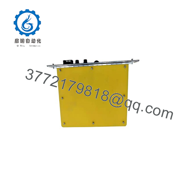
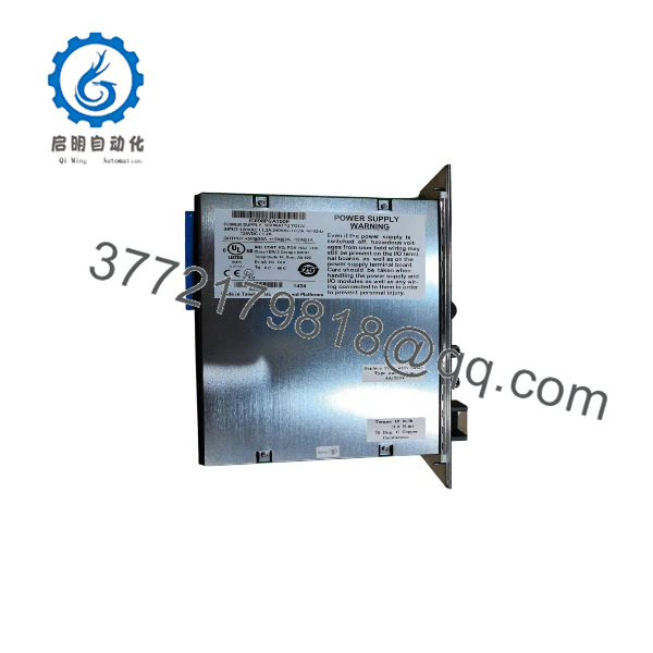
- IC698PSA100
- IC698PSA100
Installation & Configuration Guide
Stage 1: Pre-Installation Preparation — 5 to 10 Minutes
⚠️ Safety First: Notify operations, place the process in a verified safe state, and complete lockout/tagout on the incoming AC or DC supply. Wait at least 5 minutes for capacitor discharge, then verify the absence of hazardous voltage with a properly rated multimeter.
Tools Required:
- ESD wrist strap and grounded ESD mat
- PH1 screwdriver
- Multimeter rated for the installation voltage
- Wire labels and marker
- Smartphone or camera for photographs
- Insulated screwdriver suitable for the cabinet terminals
Data Backup and Inspection:
- Confirm the replacement is IC698PSA100, not the higher-capacity IC698PSA350 or another RX7i supply.
- Record the rack catalog number, installed modules, input voltage, and supply alarm status.
- Photograph the incoming power wiring, terminal labels, rack position, and front-panel LEDs.
- Check the rack power budget. The supply provides 100 W total; do not add the three rail ratings together without checking the manufacturer’s output-power limits.
- Inspect the replacement for corrosion, cracked insulation, rework marks, damaged connectors, or missing hardware.
- Request the supplier’s serial-number photographs, functional test report, condition statement, and warranty terms.
Stage 2: Removing the Old Module — 5 Minutes
- Remove the rack cover or front protective hardware as required.
- Verify the incoming supply is isolated with the multimeter.
- Label each incoming wire before disconnecting it. Do not pull on the conductor or force the terminal.
- Loosen the retaining screws or locking mechanism.
- Release the rack retention tabs and pull the power supply straight out.
- Inspect the backplane connector for bent pins, dust, discoloration, or signs of overheating.
- Keep the removed supply for reference until the replacement has passed load and alarm testing.
Stage 3: Installing the New Module — 5 to 10 Minutes
- Put on the grounded ESD wrist strap and verify the replacement nameplate.
- Confirm that the supply is installed in Slot 0, the leftmost position of the RX7i rack.
- Compare the terminal layout and connector arrangement with the photographs of the original unit.
- Slide the module into the rack guides without twisting it.
- Press the module firmly into the backplane until fully seated.
- Secure the retaining screws or locking tabs.
- Reconnect the incoming AC or DC wiring using the correct polarity and protective-earth arrangement.
- Tighten terminals to the applicable OEM or terminal-block torque specification.
- Check that no wire strands are exposed and that the cabinet wiring cannot contact adjacent terminals.
Self-Checklist:
- IC698PSA100 model verified
- [] Slot 0 position confirmed
- [] Input voltage matches the supply rating
- [] AC/DC wiring and polarity verified
- [] Protective earth connected
- [] Terminals tightened
- [] Module fully seated
- [] Rack power calculation completed
Stage 4: Power-On and Testing — 10 to 15 Minutes
- Check resistance between the input conductors and ground for an unexpected short before applying power.
- Confirm the measured incoming voltage is within the applicable range: 85 to 264 VAC or 100 to 150 VDC.
- Energize the rack with field loads disabled where the process procedure permits.
- Observe the power-supply LEDs and the CPU status. Record any fault or loss-of-power indication.
- Measure the backplane rails at an approved test point: +5 VDC, +12 VDC, and −12 VDC.
- Confirm the +5 VDC rail remains within 4.875 to 5.25 VDC under normal rack load.
- Confirm the CPU, I/O, and communication modules complete their startup sequence.
- Test the rack under normal load and monitor the supply for excessive heating, repeated alarms, or output instability.
- Restore field devices and return the process to service under the approved operating procedure.
⚠️ Troubleshooting Note: If the CPU does not start, first check Slot 0 seating, input voltage, rack compatibility, and the +5 VDC rail. If the supply repeatedly faults, calculate the actual rack load and inspect for a shorted module or backplane fault before replacing another power supply.
Frequently Asked Questions (FAQ)
Can I hot-swap the ?
Do not remove this power supply under power unless the exact RX7i rack, system design, and site procedure explicitly permit it. The module connects directly to the rack power and backplane interface. Shut down the rack, isolate the incoming source, complete lockout/tagout, and verify zero energy before removal.
Is the obsolete?
The belongs to the legacy PACSystems RX7i platform. It remains available through surplus and industrial automation distributors, but inventory may include factory-sealed, new-surplus, used, and refurbished units. Require a clear condition statement and recent photographs before placing an order.
What is the direct replacement for the ?
The IC698PSA100E may be a later related version, but do not substitute it solely because the base catalog number appears similar. Verify the chassis, input source, firmware or hardware revision requirements, mechanical fit, output ratings, and OEM documentation. The IC698PSA350 is not a direct substitute simply because it supplies more power; its rack loading and input characteristics differ.
Can I use the in any RX7i rack?
It is intended for PACSystems RX7i racks and installs in Slot 0. Confirm the rack catalog number and installation manual before installation, especially where redundant supplies, expansion racks, or mixed VME modules are involved. The supply must also match the available AC or DC input source.
Why does the supply provide three output voltages?
The RX7i backplane uses multiple regulated rails for the CPU, I/O, and communication modules. The provides +5 VDC, +12 VDC, and −12 VDC, with the total output limited to 100 W. A rack can remain under the individual current limits while still exceeding the total allowable power, so calculate the complete rack load.
Is the replacement genuinely new?
That depends on the specific inventory lot. “New Original,” “New Surplus,” and “Refurbished (tested)” describe different conditions and should not be treated as interchangeable. For new-surplus stock, request unopened packaging photographs, serial-number traceability, and a written warranty; for refurbished stock, request the test report and repair history.
What testing should the supplier provide?
A credible test package should include visual inspection, serial-number traceability, power-on LED verification, output-voltage measurements, alarm testing, and a continuous load test. The inspection should include a 500 V insulation-resistance test where applicable, ground-continuity verification, QC sign-off, and photographs of the final packaging. Test videos and photos should be available upon request; verify precise compatibility against the OEM datasheet before installation.



