
 WhatsApp: +86 16626708626
 Email:
  Phone: +86 16626708626
Description
3. Key Technical Specifications
| Parameter | Value |
|---|---|
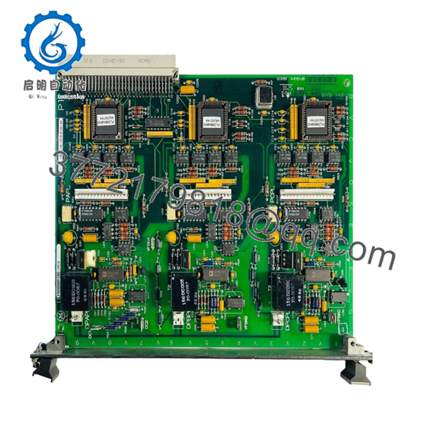
| Part Number | IS200BPIBG1ADB |
| Manufacturer | General Electric |
| Product Type | Bridge Personality Interface Board |
| Functional Description | Phase Logic Interface Module |
| Series | Speedtronic Mark VI IS200 |
| Primary Function | IGBT gate-driver interface and fault processing |
| Supported Driver Boards | Up to 6 in bridge mode |
| Input Channels | 40 discrete logic inputs |
| Logic Supply | Isolated +5 V DC @ 500 mA |
| Power Input | 17.7 VAC transformer input or 5 V DC |
| Memory Device | Serial 1024-bit ID memory chip |
| Connector Type | VME backplane + plug/stab connectors |
| Application | Gas turbine and industrial drive systems |
| Cooling Method | Passive cabinet airflow |
| Mounting Style | VME rack-mounted PCB |
| Approximate Weight | 0.8 kg |
| Condition Options | New Surplus / Refurbished Tested |
| Availability | Limited surplus inventory globally |
Technical references identify the IS200BPIBG1ADB as a GE Mark VI phase logic interface module used between drive racks and IGBT gate-driver boards for fault capture and signal conditioning.
4. Product Introduction
The GE IS200BPIBG1ADB is a Bridge Personality Interface Board used in GE Speedtronic Mark VI turbine and drive control systems. The module interfaces phase sensing logic, DC-link monitoring signals, and IGBT gate-driver communication within VME-based Mark VI racks.
In field deployments, this board commonly appears in medium-voltage drive cabinets and turbine control systems where fast fault reporting and phase timing integrity are critical. Engineers usually replace this module after intermittent gate-driver communication faults, startup synchronization alarms, or aging component failures affecting phase sensing accuracy.
- IS200BPIBG1ADB
- IS200BPIBG1ADB
5. Installation & Configuration Guide
Stage 1: Pre-Installation Preparation (Estimated Time: 10 Minutes)
⚠️ Safety First
- Notify operations and verify the drive or turbine system is in a safe shutdown state.
- Lock out and tag out all incoming control and power cabinet feeds.
- Wait at least 5 minutes for DC bus capacitors to discharge fully.
❗ Medium-voltage drive cabinets can retain dangerous DC-link voltage after shutdown. Verify discharge with a meter. Never trust the HMI status alone.
Tools Required
- Grounded ESD wrist strap
- PH1 screwdriver
- Fluke 115 multimeter
- Wire markers
- Smartphone for documentation photos
- Flashlight for rack inspection
Data Backup
- Export current Mark VI configuration files.
- Photograph:
- Rack slot position
- Ribbon cable routing
- Jumper positions
- Connector orientation
- Record firmware revisions from associated control processors.
I’ve seen technicians install the correct board into the wrong VME slot because multiple IS200 modules looked nearly identical during outage pressure. One photo beforehand avoids that mess entirely.
Stage 2: Removing the Old Module (Estimated Time: 5 Minutes)
- Remove cabinet covers carefully.
- Label all connectors and cables before removal.
- Disconnect stab-on and ribbon connectors evenly.
- Release retention hardware or VME extraction tabs.
- Pull the board straight outward to protect backplane pins.
- Inspect:
- VME connector condition
- Dust buildup
- Heat discoloration
- Bent pins
- Oxidation near connector areas
⚠️ Note: Keep the old board available until the replacement completes full operational testing.
Mark VI cabinets often contain undocumented field modifications added during previous outages. Never assume the prints are fully current.
Stage 3: Installing the New Module (Estimated Time: 10 Minutes)
- Wear the grounded ESD wrist strap before touching the PCB.
- Verify exact model:
- IS200BPIBG1ADB
- Inspect the replacement board for:
- Cracked solder joints
- Rework marks
- Connector damage
- Corrosion
- Configuration Clone (Crucial):
- Match all jumper settings
- Verify connector orientation
- Confirm driver-board interface assignments
- Insert the board carefully into the VME rack guides.
- Press evenly until fully seated into the backplane connector.
- Tighten retention screws securely.
- Reconnect all interface wiring and ribbon cables.
Self-Checklist
- Board revision verified
- Connectors fully seated
- Retention hardware secured
- No bent backplane pins
- No loose tools inside cabinet
❗ This is the most common rookie mistake, but experienced engineers still get caught by it during emergency outages. A partially seated VME board can generate intermittent communication faults that waste half a shift.
Stage 4: Power-On & Testing (Estimated Time: 10–15 Minutes)
Pre-Power Check
- Verify no shorts exist on the control power rail.
- Confirm cabinet grounding continuity.
- Inspect all VME connectors for proper seating.
Power-On Steps
- Energize the control rack only.
- Observe startup sequence and diagnostics.
- Verify communication with associated gate-driver boards.
- Connect the engineering workstation.
- Confirm:
- Phase sensing signals
- Fault reporting status
- Driver-board communication
- Reload configuration data if required.
- Perform dry-run testing before enabling field outputs.
⚠️ Troubleshooting Note
- Communication faults immediately after startup often indicate:
- Firmware mismatch
- Incorrect connector placement
- Partially seated VME connector
- Wrong board revision
I’ve personally seen a drive startup delayed nearly two days because a replacement board revision altered communication timing slightly between gate-driver interfaces and the main controller.
6. Frequently Asked Questions (FAQ)
Q1: Can I hot-swap the IS200BPIBG1ADB under power?
No. Do not hot-swap this board.
The Mark VI platform was not designed for live insertion of VME interface boards handling phase logic and gate-driver communication. Pulling the module live can corrupt fault reporting or damage the backplane.
Q2: What exactly does the IS200BPIBG1ADB do?
The board acts as a phase logic and interface module between the Mark VI control rack and IGBT gate-driver boards. It processes phase sensing signals, monitors DC-link status, and captures driver faults for reporting back to the controller.
Q3: Is this module obsolete?
Yes. The IS200BPIBG1ADB is considered obsolete from the OEM production perspective.
Most available inventory now comes from:
- New surplus stock
- Plant spare inventory
- Professionally refurbished boards
Plants still operating Mark VI systems continue buying these boards for lifecycle extension and outage support.
Q4: What is the biggest installation mistake with this module?
❗ Connector mismatch and incomplete seating.
The board uses multiple interface connectors and VME backplane engagement points. A connector that looks seated but isn’t fully locked can create intermittent phase faults that are extremely difficult to diagnose.
Take photos before removal. Every time.
Q5: Will replacing this board erase my application logic?
Usually no, because application logic resides elsewhere in the Mark VI architecture.
Still, before shutdown:
- Export configuration backups
- Record firmware revisions
- Document jumper settings
I’ve seen projects where newer board revisions introduced slight timing differences that triggered unexpected drive fault alarms during commissioning.
Q6: Why are some surplus prices much lower than OEM historical pricing?
Because GE no longer manufactures many Mark VI boards through standard production channels.
Pricing now depends on:
- Remaining global inventory
- Outage demand
- Board condition
- Testing quality
- Warranty coverage
Lower pricing alone does not automatically indicate counterfeit hardware, but serious suppliers should provide:
- Actual board photos
- Electrical test reports
- Startup verification
- Serial documentation
Q7: What QC testing should a supplier perform before shipment?
Minimum acceptable testing should include:
- Visual inspection under magnification
- Serial and revision verification
- 500 V insulation resistance testing (>10 MΩ)
- Ground continuity verification
- VME communication testing
- Gate-driver interface simulation
- 24-hour powered burn-in testing
- ESD-safe anti-static packaging
Good suppliers typically test these boards on genuine GE Mark VI racks and can provide startup photos or test videos upon request.
Keep these checks in mind and you’ll avoid most field replacement headaches.


