
 WhatsApp: +86 16626708626
 Email:
  Phone: +86 16626708626
Description
Key Technical Specifications
| Parameter | Specification |
| Board Identifier | CABP (Control Assembly Backplane) |
| System Compatibility | GE Mark VI Control Systems (R, S, T, and C Cores) |
| Slot Configuration | Supports VME-style processor and I/O cards |
| Input Voltage | 28 VDC (Nominal) via Power Distribution |
| Communication Bus | Parallel high-speed backplane bus |
| Revision Level | G1B |
| Connector Type | High-density pin-and-socket (DIN 41612 style) |
| Operating Temp | -30 to +65°C (-22 to 149°F) |
| Mounting | Cabinet Rack Assembly |

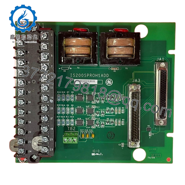
- IS200CABPG1B
Product Introduction
The GE IS200CABPG1B is the central Control Assembly Backplane (CABP) for the Mark VI Speedtronic system. It acts as the “nervous system” of the control core, providing the physical slots and electrical pathways required for processor cards, communication modules, and I/O interface boards to communicate with one another. Without a fully functional CABP, the internal high-speed data bus cannot maintain the synchronization necessary for Triple Modular Redundant (TMR) voting.
This G1B revision is engineered for high reliability in the electrical noise-heavy environments of power plants. It features robust power traces to distribute stable DC voltage to all seated cards and gold-plated connector pins to prevent oxidation over years of service. For engineers performing a rack overhaul or recovering from a catastrophic backplane short, this “New Surplus” board is the critical foundation needed to restore the control core’s integrity.
Installation & Configuration Guide
Stage 1: Pre-Installation Preparation (Estimated Time: 30 mins)
- ⚠️ Safety First: Replacing a backplane is a major “open-heart” surgery for the control system. The entire control core (R, S, or T) must be completely powered down. Ensure all upstream DC breakers are locked out.
- Tools Required: Phillips #2 screwdriver, ESD mat, canned air (for dust removal), and an inspection mirror.
- Labeling: Before pulling any cards, label every slot. A card inserted into the wrong slot on a new backplane can cause a bus conflict or hardware damage.
Stage 2: Removing the Old Backplane
- Disconnect all external ribbon cables and power feeds attached to the backplane or the cards.
- Remove all processor and I/O cards from the rack and place them on ESD mats.
- Unscrew the mounting bolts securing the IS200CABPG1B to the cabinet frame.
- Carefully lift the backplane out. Inspect the cabinet stand-offs for any signs of arcing or debris that could cause a short on the new board.
Stage 3: Installing the New Module (Estimated Time: 45 mins)
- Visual Audit: Check the new IS200CABPG1B for any bent pins in the high-density connectors. Even one bent pin can prevent a card from seating and ruin the backplane.
- Align the backplane with the mounting holes and hand-tighten the screws first to ensure alignment.
- Torque the screws firmly to ensure a solid chassis ground.
- Re-insert the control cards into their original slots. You should feel a firm “click” as they seat into the backplane connectors.
- Self-Checklist: [ ] No bent pins, [ ] All cards seated, [ ] Grounding screws tight.
Stage 4: Power-On & Testing
- Apply power to the rack.
- Monitor the boot sequence of the processor cards. The backplane itself has no LEDs, but the successful “Ready” status of the cards indicates the bus is healthy.
- Use the Mark VI Toolbox software to verify that all cards in the rack are communicating and that there are no “VME Bus Errors.”
- Check the diagnostic logs for any “Address Mismatch” alarms, which would indicate a card is not seated properly or a slot-addressing fault.
Frequently Asked Questions (FAQ)
Q: Can I use an IS200CABPG1B to replace a G1A revision?
A: Yes. The G1B is a direct successor to the G1A and maintains the same physical dimensions and electrical pinouts. The G1B usually includes improved solder mask and trace reinforcements to handle thermal cycling better than the original version.
Q: Is there any firmware to “flash” onto the backplane?
A: No. The CABP is a passive interconnect board. It has no microprocessor or software. Its only “logic” is the physical routing of traces between the connectors. All intelligence resides on the cards you plug into it.
Q: Why is my rack failing to boot after replacing the backplane?
A: The most common culprit is a bent pin in one of the slots. If a pin is bent and touching another, it will short the VME bus and prevent any card in the rack from communicating. Pull the cards one by one and use a flashlight to inspect the backplane connectors.
Q: Does this backplane provide the power to the field devices (valves, sensors)?
A: Not directly. The CABP distributes logic power (+5V, +/-15V, 24V) to the control cards. The field power usually stays on the terminal boards (T-Boards) and doesn’t pass through this backplane bus.
Q: Can I replace the backplane while other TMR cores (S and T) are running?
A: Yes, if you are only replacing the “R” core backplane, the “S” and “T” cores will stay online and maintain turbine control. However, you will be running in a “Degraded” (simplex or dual) mode, so work efficiently to minimize the time spent without full redundancy.


