
 WhatsApp: +86 16626708626
 Email:
  Phone: +86 16626708626
Description
3. Key Technical Specifications
| Parameter | Value |
|---|---|
| Manufacturer | GE (General Electric) |
| Model Number | IS200EAUXH1A |
| Product Type | Exciter Auxiliary Board |
| Control Platform | GE Mark VI / EX2100 |
| Application | Generator excitation control |
| Board Function | Auxiliary signal interface and control expansion |
| PCB Type | Mark VI printed circuit board assembly |
| Interface Type | Excitation system internal interface |
| Rack Compatibility | GE EX2100 excitation control architecture |
| Input Power | Supplied through excitation control rack |
| Configuration Tool | GE ToolboxST |
| Replacement Type | Direct hardware replacement (subject to revision verification) |
| Operating Temperature | Refer to GE Mark VI hardware specifications |
| Installation Method | Control cabinet rack mounting |
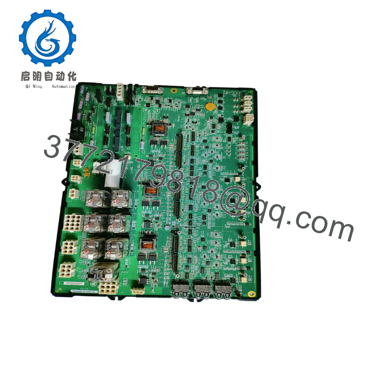
The GE IS200EAUXH1A is an auxiliary interface board used within GE Mark VI and EX2100 excitation control systems. The board provides signal interface functions between excitation control components and the overall Speedtronic control architecture.
4. Product Introduction
The GE IS200EAUXH1A is a Mark VI excitation auxiliary board designed for generator excitation control applications. It provides interface functions within GE EX2100 excitation systems, supporting communication and signal exchange between excitation hardware components.
This legacy GE board is commonly maintained in power generation facilities where Mark VI excitation systems remain operational. Replacement requires verification of board revision, ToolboxST configuration, cabinet wiring, and the existing excitation hardware architecture before installation.
5. Installation & Configuration Guide
Stage 1: Pre-Installation Preparation (15 Minutes)
⚠️ Safety First
- Notify plant operations before starting maintenance.
- Confirm the generator excitation system is in a safe shutdown state.
- Apply Lockout/Tagout (LOTO).
- Isolate excitation cabinet power.
- Wait at least 5 minutes for capacitor discharge.
Tools Required
- ESD wrist strap
- PH1 screwdriver
- Fluke 115 multimeter
- Wire labels
- Smartphone for wiring photographs
- Laptop with GE ToolboxST
Data Backup
Before removing the board:
- Save the current Mark VI/EX2100 configuration.
- Record rack position and slot location.
- Photograph all terminal wiring.
- Document board serial number and revision.
- Record any jumper settings.
- Export current ToolboxST project files.
Stage 2: Removing the Old Module (10 Minutes)
- Remove the excitation cabinet front cover.
- Verify all power sources are isolated.
- Label every connected wire before removal.
- Disconnect terminal wiring carefully.
- Release rack retention hardware.
- Pull the board straight out to protect backplane connectors.
Inspect:
- Backplane pins
- Terminal connectors
- PCB surface condition
- Signs of overheating or contamination
⚠️ Keep the original IS200EAUXH1A board until the replacement completes operational testing.
Stage 3: Installing the New Module (15 Minutes)
- Wear an ESD wrist strap before handling the replacement board.
- Verify the replacement:
GE IS200EAUXH1A
- Compare:
- Board revision
- Hardware ID label
- Connector locations
- Jumper configuration
- Clone the original configuration:
- Match jumper positions.
- Confirm rack location.
- Verify terminal assignments.
- Insert the board into the rack until fully seated.
- Reconnect wiring using appropriate torque settings.
Installation Checklist
- Board revision verified
- Jumper settings matched
- Wiring secured
- Rack locking tabs engaged
Stage 4: Power-On & Testing (30 Minutes)
Pre-Power Check
- Verify no short circuit exists on cabinet power rails.
- Confirm grounding continuity.
- Check terminal connections.
- Verify correct board installation position.
Power-On Steps
- Power up the control rack only.
- Observe board status indicators.
- Connect GE ToolboxST.
- Verify hardware recognition.
- Confirm firmware/configuration compatibility.
- Download configuration if required.
- Perform excitation system I/O verification.
⚠️ Troubleshooting Note
- Red fault indication: Check board revision mismatch or configuration errors.
- No communication: Verify rack position, backplane connection, and ToolboxST hardware configuration.
- Unexpected excitation alarms: Confirm terminal wiring and parameter assignments.

- IS200EAUXH1A
SOP Quality Verification
1. Inbound Inspection & Traceability
Each IS200EAUXH1A unit should receive:
- OEM label and serial number verification
- Source traceability review
- Anti-counterfeit inspection
- PCB visual inspection
Inspection criteria:
- No corrosion
- No scratches
- No unauthorized rework marks
- No UV yellowing
- Connector condition verified
Accessory audit:
- Manuals where supplied
- Factory documentation where available
- Warranty records
2. Live Functional Testing
Testing should be performed on a genuine GE Mark VI / EX2100 excitation test rack.
Verification steps:
- Power-on self-test
- LED/status indication check
- Backplane communication verification
- Excitation interface signal simulation
- Input/output signal validation
- Continuous operation exceeding 24 hours
- Thermal monitoring
A formal Test Report should be generated.
Test photos and videos should be available upon request.
3. Electrical Parameter Testing
Required electrical checks:
- 500 V Megger insulation resistance test (>10 MΩ where applicable)
- Ground continuity verification
- Power supply measurement
- Connector contact inspection
4. Firmware & Configuration Verification
Document:
- Hardware revision
- Board identification data
- ToolboxST compatibility
- Existing configuration backup
Configuration records should include:
- Rack position
- Jumper settings
- Terminal wiring photos
5. Final QC & Packaging
Final preparation:
- QC inspector sign-off
- Anti-static ESD bagging
- Bubble wrap protection
- Heavy-duty corrugated boxing
- QC Passed label with inspection date
Technical Pitfalls & Survival Guide
❗ Firmware and Hardware Revision Mismatch
GE Mark VI systems are sensitive to hardware revision differences.
I have seen maintenance teams install a visually identical replacement board only to receive configuration faults during startup. The issue was not the board failure; the ToolboxST hardware definition did not match the installed revision.
Always document the original revision before ordering.
❗ Jumper Configuration Errors
This is one of the most common mistakes during legacy board replacement.
Take a clear photograph before removing the board. Match every jumper position exactly.
A single incorrect setting can prevent proper excitation system initialization.
❗ Terminal Wiring Changes
Never assume a similar GE board uses identical terminal assignments.
Even within the Mark VI family, connector definitions can vary between revisions.
Always verify the GE wiring diagram before reconnecting field signals.
❗ Rack Slot Location
Mark VI systems identify hardware by configured location.
Installing the IS200EAUXH1A into the wrong rack position can generate hardware mismatch alarms even when the board itself operates correctly.
❗ Electrostatic Discharge (ESD)
The board contains sensitive semiconductor devices.
Always:
- Wear a grounded wrist strap.
- Use an ESD-safe work surface.
- Avoid touching PCB components.
Keep these checks in mind and you’ll save significant rework time during GE Mark VI excitation maintenance.
6. Frequently Asked Questions (FAQ)
Q1. What is the GE IS200EAUXH1A used for?
The IS200EAUXH1A is an auxiliary interface board used in GE Mark VI and EX2100 excitation control systems. It supports signal interface functions inside generator excitation control cabinets.
Q2. Is the IS200EAUXH1A still manufactured?
No. The IS200EAUXH1A is a legacy GE Speedtronic component. Available units are typically New Original (New Surplus) or Refurbished (tested).
Q3. Can I hot-swap the IS200EAUXH1A?
No.
For most GE Mark VI excitation applications, power should be removed before replacing control boards. Hot removal can damage connectors and create additional system faults.
Q4. Will replacing this board erase my excitation configuration?
The board itself does not store the complete Mark VI/EX2100 application configuration.
However, always back up the ToolboxST project before replacement because configuration mismatch can prevent successful commissioning.
Q5. Why is this module priced lower than OEM replacement pricing?
Legacy industrial automation components often enter the aftermarket through surplus inventory, plant upgrades, and discontinued system support channels.
The important checks are:
- Hardware revision
- Serial traceability
- Functional test records
- Warranty terms
Q6. What should I verify before ordering an IS200EAUXH1A?
Confirm:
- Exact model: IS200EAUXH1A
- Hardware revision
- Existing Mark VI/EX2100 cabinet configuration
- Rack position
- ToolboxST compatibility
- Terminal wiring
Verify precise compatibility with OEM documentation before installation.
Q7. What testing should be requested before shipment?
For generator excitation applications, request:
- Serial number verification
- Visual inspection report
- Mark VI/EX2100 rack test results
- Signal interface testing
- 24-hour operational test record
- Firmware/configuration documentation
- ESD-safe packaging confirmation
These records help reduce commissioning risk when maintaining legacy GE Speedtronic excitation systems.



