
 WhatsApp: +86 16626708626
 Email:
  Phone: +86 16626708626
Description
3. Key Technical Specifications
| Parameter | Value |
|---|---|
| Model Number | IS200EAUXH1ABB |
| Manufacturer | General Electric |
| Product Family | EX2100e Excitation Control |
| Product Type | Exciter Auxiliary I/O Interface Board |
| Functional Description | Auxiliary signal conditioning and interface |
| Redundancy Type | TMR (Triple Modular Redundant) |
| Control Sections | M1, M2, C |
| Contact Inputs | 3 |
| Contactor Interface | 41DC |
| Wetting Voltage | 125 VDC |
| Communication Interface | HSSL connection to UCSx controller |
| Installation | Mark VI rack/backplane mounting |
| Series Manual | GEH-6781 |
| Condition | New Original / New Surplus |
| Warranty | 12 months |
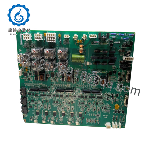
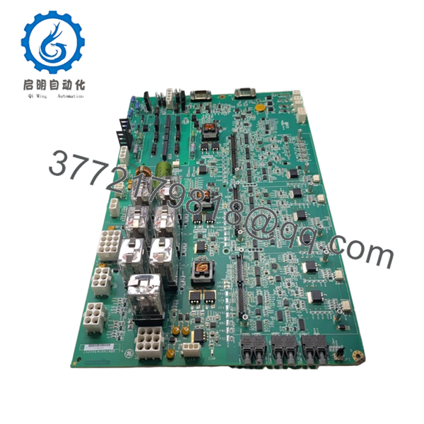
The IS200EAUXH1ABB is identified as an EX2100e Exciter Auxiliary Interface Board used in GE excitation systems. Public references indicate TMR support, HSSL communication with UCSx controllers, and signal-conditioning functions.
4. Product Introduction
The GE IS200EAUXH1ABB is an Exciter Auxiliary I/O Interface Board used in GE EX2100e excitation systems and related Mark VI environments. The board supports auxiliary signal handling, signal conditioning, field-ground related functions, and communication with system controllers.
In field deployments, auxiliary boards rarely get attention until startup problems begin appearing. I’ve seen systems report unstable excitation behavior that initially looked like controller faults. The actual cause turned out to be an auxiliary interface board failure creating misleading signal conditions upstream of the control system. The board communicates with UCSx controllers through an HSSL interface path.

- IS200EAUXH1ABB
- IS200EAUXH1ABB
5. Installation & Configuration Guide
Stage 1: Pre-Installation Preparation (Estimated Time: 10 minutes)
⚠️ Safety First: Notify operations of expected downtime. Confirm the excitation system is in a safe state. Apply lockout/tagout procedures. Remove cabinet power and wait 5 minutes for capacitor discharge.
Tools Required
- ESD wrist strap
- PH1 screwdriver
- Fluke 115 multimeter
- Wire labels
- Smartphone for photos
- ESD work surface
Data Backup
- Export current controller and excitation configuration.
- Document cabinet slot locations.
- Photograph connector positions and cable routing.
- Capture jumper settings and labels.
- Record hardware revision details.
⚠️ EX2100e cabinets frequently carry field modifications that never reached the drawing package. I trust cabinet photos more than old documentation.
Stage 2: Removing the Old Module (Estimated Time: 5 minutes)
- Open cabinet access panels.
- Label every cable before disconnecting.
- Disconnect wiring carefully.
- Release locking hardware.
- Pull the board straight outward.
⚠️ Do not twist the board.
I watched a technician rush a board extraction and damage a backplane connector. A simple module replacement became a two-day outage.
Inspect:
- Bent pins
- Corrosion
- Dust contamination
- Heat discoloration
- Loose hardware
⚠️ Keep the original board available until startup verification finishes.
Stage 3: Installing the New Module (Estimated Time: 5–10 minutes)
- Wear ESD protection before handling.
- Verify exact model number: IS200EAUXH1ABB
- Configuration Clone (Crucial): Match all jumpers and hardware settings exactly.
- Align card guides carefully.
- Insert evenly until seated.
- Reconnect all field wiring.
Self-Checklist:
[ ] Jumpers copied
[ ] Wiring secured
[ ] Connectors seated
[ ] Retainers locked
⚠️ This is the most common rookie mistake, but it happens constantly. Take a picture before removal. I can’t stress this enough.
Stage 4: Power-On & Testing (Estimated Time: 10 minutes)
Pre-Power Check
Use a multimeter to verify no short exists on the 24 VDC rail.
Power sequence:
- Energize rack only
- Observe LED startup sequence
- Verify communication status
- Connect engineering workstation
- Validate excitation signals
- Perform dry-run I/O tests
Expected indications:
- Green RUN = Normal
- Red ERR = Fault
⚠️ Troubleshooting Note:
Solid fault indications after installation frequently point toward revision mismatch or communication path issues.
Technical Pitfall & Survival Guide
❗ Firmware Revision Mismatch
This causes more outage pain than many engineers expect.
I’ve seen replacement hardware installed with a revision difference that looked minor on paper. The system generated repeated communication alarms and everyone chased wiring first.
Avoidance:
- Document existing revisions
- Match firmware when ordering
- Verify hardware compatibility before shutdown
❗ DIP Switch / Jumper Misconfiguration
Take pictures before touching anything.
Factory defaults almost never match operating systems.
❗ Terminal and Connector Variations
Even GE hardware with similar model numbering can differ.
Always verify:
- Connector orientation
- Pin assignments
- Grounding methods
- Wiring diagrams
Never wire from memory.
❗ Power Budget Calculations
Auxiliary hardware adds up.
Maintain 20% spare capacity on cabinet power calculations.
❗ ESD Damage
I once watched an engineer handle an interface board during winter maintenance without a grounding strap. Startup failed immediately.
That outage became expensive very quickly.
Use:
- Grounded wrist straps
- ESD-safe workstations
- Anti-static handling procedures
Keep these checks in mind and you’ll save yourself 90% of typical rework time.
6. Frequently Asked Questions (FAQ)
Q1: Can I hot-swap IS200EAUXH1ABB?
No.
Do not replace this board under power. GE EX2100e hardware of this generation was not designed for powered insertion. You risk backplane damage and communication faults.
Q2: What exactly does IS200EAUXH1ABB do?
The board functions as an Exciter Auxiliary Interface Board and handles auxiliary signals, signal conditioning, and field-ground related functions while interfacing with UCSx controllers through HSSL communications.
Q3: Is IS200EAUXH1ABB obsolete?
Yes.
Current inventory mainly comes from controlled surplus channels and specialist industrial suppliers rather than active GE production. Available public inventory references indicate limited stock conditions.
Q4: Is this really new inventory?
Usually “New Original” means unused OEM surplus inventory rather than recently manufactured stock.
Request:
- Serial numbers
- Packaging photos
- Date codes
- Functional test reports
Q5: What is the simplex version of this board?
Public documentation identifies the H2A version as the simplex variant while H1A supports TMR architecture. Verify compatibility before installation.
Q6: Will replacing this board erase my configuration?
Usually no.
Logic and primary configuration data normally reside elsewhere in the architecture. Still, back up everything before touching hardware.
I’ve seen undocumented field edits surprise experienced teams.
Q7: How do you verify functionality before shipment?
Inspection sequence:
- OEM source verification and traceability review
- Anti-counterfeit checks and serial validation
- Visual inspection for scratches, corrosion, UV yellowing, and rework marks
- Functional testing using compatible GE hardware where available
- Communication handshake verification
- 500 V Megger insulation test (>10 MΩ)
- QC sign-off and anti-static packaging
Test photos and startup videos are available upon request.


