
 WhatsApp: +86 16626708626
 Email:
  Phone: +86 16626708626
Description
3. Key Technical Specifications
| Parameter | Value |
|---|---|
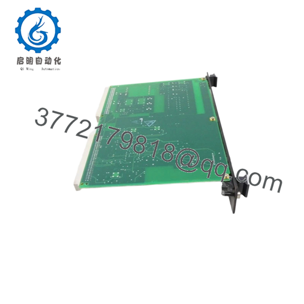
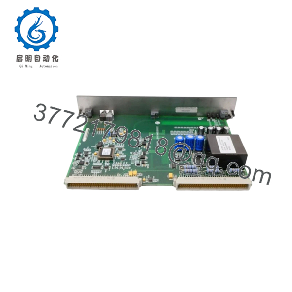
| Manufacturer | GE General Electric |
| Model Number | IS200EGDMH1AAB |
| Series | Mark VI Speedtronic / EX2100 |
| Product Type | Exciter Ground Detector Module |
| Functional Description | Generator field leakage detection |
| Application | EX2100 excitation systems |
| Detection Capability | AC and DC field ground leakage |
| System Configuration | Simplex or redundant excitation systems |
| Redundant System Support | Controller, M1, M2 configurations |
| Mounting Style | Double-height, double-slot module |
| Backplane Type | EPBP Exciter Power Backplane |
| Backplane Connectors | P1 and P2 |
| Fiber-Optic Interfaces | HFBR2528 receive, HFBR1528 transmit |
| LED Indicators | Power, Master Select, Master Active |
| PCB Coating | Conformal coating |
| Operating Temperature | −30 °C to +65 °C typical industrial range |
| Storage Temperature | −40 °C to +85 °C |
| Humidity Rating | 5% to 95% non-condensing |
| Approximate Weight | 0.4–0.8 kg |
| Warranty | 12 Months |
4. Product Introduction
The GE IS200EGDMH1AAB is an Exciter Ground Detector Module used in GE EX2100 and Mark VI excitation control systems. The module monitors generator field circuits for AC and DC leakage current to ground, helping protect excitation equipment and generator insulation systems from developing ground faults.
In operating power plants, this module is commonly installed in excitation cabinets using the EPBP backplane architecture. Engineers typically maintain the exact IS200EGDMH1AAB revision during outages because mismatched revisions or incorrect redundant configuration settings can trigger nuisance alarms or exciter shutdown conditions during startup.
5. Installation & Configuration Guide
Stage 1: Pre-Installation Preparation (Estimated Time: 10 Minutes)
⚠️ Safety First
- Notify operations and obtain outage approval.
- Verify the excitation system and generator are offline.
- Apply lock out/tag out procedures.
- Wait at least 5 minutes for excitation discharge circuits to stabilize.
⚠️ Excitation cabinets can retain hazardous voltage after shutdown. Verify the field discharge path with a meter before touching internal components.
Tools Required
- ESD wrist strap
- PH1 screwdriver
- Fluke 115 multimeter
- Fiber-optic cleaning kit
- Wire labels
- Smartphone for cabinet photos
Data Backup
- Export EX2100 configuration data.
- Photograph:
- P1/P2 connector locations
- Fiber-optic routing
- Cabinet slot location
- Record redundant controller assignment:
- C
- M1
- M2
- Document any field modifications.
❗ This gets skipped constantly during emergency outages. Then the team spends hours trying to determine which board was configured as M1 versus M2.
Stage 2: Removing the Old Module (Estimated Time: 5–10 Minutes)
- Open the excitation cabinet access panel.
- Label all fiber and backplane connections.
- Disconnect optical connectors carefully.
⚠️ Never bend fiber cables sharply. Damaged optical cables create intermittent communication faults that look like controller failures.
- Remove retaining hardware.
- Pull the module straight outward without twisting.
- Inspect:
- Backplane pins
- Optical connectors
- Dust buildup
- Heat discoloration
- Capacitor leakage signs
Field Reminder
Keep the original module nearby until startup is complete. I’ve seen technicians remove the wrong redundant assignment module and spend half a shift sorting out controller ownership conflicts.
Stage 3: Installing the New Module (Estimated Time: 10 Minutes)
- Wear a grounded ESD strap before opening the anti-static packaging.
- Verify the exact model number:
- IS200EGDMH1AAB
- Confirm revision markings match the original module.
Configuration Clone (Crucial)
- Replicate all jumper and configuration settings exactly.
- Verify simplex or redundant assignment settings.
- Confirm fiber-optic cable orientation and seating.
- Verify P1/P2 connector alignment.
❗ This is the most common rookie mistake in EX2100 systems. One incorrect controller assignment can generate immediate redundant controller conflicts during startup.
- Insert the module evenly into the EPBP backplane.
- Ensure the board seats fully.
- Tighten retaining screws evenly.
- Reconnect fiber and control wiring carefully.
Self-Checklist
- Model verified
- Redundant assignment correct
- Fiber connectors secure
- Board fully seated
- Grounding verified
Stage 4: Power-On & Testing (Estimated Time: 15–20 Minutes)
Pre-Power Check
- Verify no shorts exist on the cabinet DC rail.
- Check grounding continuity.
- Inspect optical cable seating and cleanliness.
Power-On Steps
- Energize the excitation control rack only.
- Observe LED startup sequence:
- Power LED
- Master Select LED
- Master Active LED
- Verify communication with the EISB board.
- Confirm ground detection status through EX2100 diagnostics.
- Perform dry-run excitation testing before restoring generator operation.
⚠️ If redundant controller alarms appear immediately after startup, verify controller assignment jumpers before replacing additional hardware.
SOP Testing Performed Before Shipment
Each IS200EGDMH1AAB unit undergoes:
- Inbound Inspection & Traceability
- OEM label verification
- Serial number inspection
- Connector integrity inspection
- Anti-counterfeit visual checks
- Live Functional Testing
- Tested on a genuine EX2100 rack
- Ground leakage simulation
- Fiber-optic communication verification
- Continuous thermal load testing exceeding 24 hours
- Electrical Parameter Testing
- 500 V insulation resistance testing (>10 MΩ)
- Ground continuity verification
- Power rail stability checks
- Firmware & Configuration Verification
- Revision identification documented
- Jumper configuration archived
- Connector photographs retained
- Final QC & Packaging
- ESD-safe anti-static packaging
- Reinforced export carton
- QC sign-off with inspection date
Test videos and startup verification photos are available upon request.
- IS200EGDMH1AAB
- IS200EGDMH1AAB
6. Frequently Asked Questions (FAQ)
Q1: Can the IS200EGDMH1AAB be hot-swapped?
In some redundant EX2100 configurations, the system technically permits replacement while the exciter remains operational. However, I do not recommend treating this casually in the field.
One incorrect redundant assignment or fiber reconnection mistake can force an exciter trip. Unless the outage cost is extreme and procedures are fully validated, shut the cabinet down first.
Q2: What exactly does this module monitor?
The IS200EGDMH1AAB monitors leakage resistance between the generator field circuit and ground. It detects both AC and DC side leakage conditions across the excitation system.
This helps identify insulation breakdown before it escalates into major generator damage.
Q3: Is the IS200EGDMH1AAB obsolete?
Yes. The EX2100 and Mark VI product families are mature legacy platforms. OEM manufacturing availability is limited, so most inventory today comes from surplus stock, strategic spares, or professionally tested refurbishment channels.
Many utilities still maintain these systems because full excitation upgrades require major outage planning and commissioning effort.
Q4: What causes the most startup issues after replacement?
Redundant assignment mismatch and fiber-optic routing errors.
I’ve seen engineers install the hardware correctly mechanically, but assign two modules as “Master.” The cabinet immediately generated controller ownership alarms and blocked startup until the configuration was corrected.
Photograph everything before removal.
Q5: Will replacing this module erase excitation settings?
Normally no. The IS200EGDMH1AAB primarily handles ground detection functions rather than storing primary excitation regulation logic.
Still, always back up the EX2100 configuration first. I’ve seen undocumented site-specific adjustments disappear during rushed maintenance windows.
Q6: Why are these EX2100 boards still expensive?
Because generator downtime is expensive.
If an excitation system is unavailable waiting on one ground detector module, the plant can lose far more revenue in a single shift than the hardware cost itself. That keeps demand high for tested spare inventory with traceable QC records.
Q7: What installation mistake damages these boards most often?
ESD damage and contaminated fiber-optic connectors.
❗ I once watched an engineer reconnect optical cables with dirty fiber ends during an outage. The exciter started intermittently dropping communication packets for hours before the contamination was discovered.
Clean optical connectors every time. Don’t assume they’re fine because they “look clean.”
Keep these checks in mind and you’ll save yourself 90% of typical rework time.


