
 WhatsApp: +86 16626708626
 Email:
  Phone: +86 16626708626
Description
3. Key Technical Specifications
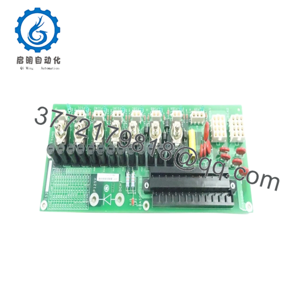
IS200EPDMG1ABA is an Exciter Power Distribution Module used in GE EX2100 excitation systems. The module distributes power to control, I/O, and protection circuits and mounts directly on the EPBP backplane assembly. It receives 125 VDC station battery input and accepts redundant AC backup feeds.
| Parameter | Value |
|---|---|
| Manufacturer | GE General Electric |
| Model | IS200EPDMG1ABA |
| Product Type | Exciter Power Distribution Module |
| Series | EX2100 / Mark VI |
| Primary Input Voltage | 125 VDC station battery |
| Backup Input | One or two 120 VAC sources |
| Ground Reference | ±62.5 V center grounded |
| Main Backplane | IS200EPBP |
| Output Distribution | EGPA, EXTB, EPSM modules |
| Output Protection | Individual fused outputs |
| Indicators | Green power status LEDs |
| Maintenance Features | On/off isolation switches |
| Dimensions | Approx. 16 × 10 × 6 cm |
| Weight | Approx. 0.3 kg |
| Manual Reference | GEI-100511 |
| Warranty | Typically 12 months |
The EPDM receives AC input through DACA converters and generates diode-coupled DC supply rails designated P125V and R125V. Individual output channels are fused and routed through the EPBP distribution architecture.
4. Product Introduction
GE IS200EPDMG1ABA is an Exciter Power Distribution Module used in GE EX2100 and Mark VI excitation systems. It distributes regulated power to exciter control, protection, and I/O hardware and mounts directly on the IS200EPBP Exciter Power Backplane assembly.
In field deployments of EX2100 systems, EPDM modules become central to cabinet reliability because a single power distribution issue can create faults across multiple boards simultaneously. Engineers typically insist on exact suffix matching because Mark VI hardware revisions occasionally introduce subtle compatibility differences that become visible only during startup. I have seen outage windows extended because someone assumed “close enough” on a suffix revision.
5. Installation & Configuration Guide
Stage 1: Pre-Installation Preparation (Estimated: 10 minutes)
⚠️ Safety First: Notify operations of scheduled downtime. Confirm the generator and excitation system are in a safe state. Apply lockout/tagout. Wait at least 5 minutes for stored energy discharge.
Tools Required
- ESD wrist strap
- PH1 screwdriver
- Fluke 115 multimeter
- Wire labels
- Smartphone for photos
- ESD work mat
- Flashlight
Data Backup
- Export EX2100 configuration files.
- Record cabinet slot information.
- Photograph wiring layouts.
- Photograph jumper and switch positions.
- Record EPBP and associated board locations.
⚠️ Excitation cabinets frequently accumulate undocumented field modifications over years of outages.
Stage 2: Removing the Old Module (Estimated: 5 minutes)
- Remove cabinet access cover.
- Label all wiring and plugs.
- Disconnect terminals carefully.
- Release retention hardware.
- Pull module straight outward.
Inspect:
- Connector damage
- Bent pins
- Heat discoloration
- Dust contamination
⚠️ Keep the old module until startup completes.
I’ve seen technicians discard failed boards immediately, then realize nobody documented switch settings.
Stage 3: Installing the New Module (Estimated: 10 minutes)
- Wear grounded ESD protection.
- Verify exact model number: IS200EPDMG1ABA
- Configuration Clone (Crucial): Replicate all DIP switches and jumpers exactly.
Check:
- Ground reference selections
- Jumper settings
- Backup feed configuration
- Switch positions
This is the most common rookie mistake, but it happens constantly. Take a picture before you pull it. I can’t stress this enough.
- Insert module carefully into guides.
- Verify complete seating against EPBP.
- Reconnect all wiring.
Self-Checklist
- DIPs match
- Wiring secured
- Lock tabs engaged
Stage 4: Power-On & Testing (Estimated: 10 minutes)
Pre-Power Check
Use a multimeter to verify no short exists on the 125 VDC supply rails.
Power-up sequence:
- Energize cabinet only
- Observe LED sequence
- Verify status indicators
- Connect engineering workstation
- Verify communication status
- Confirm power distribution outputs
Green LEDs indicate output availability.
⚠️ Troubleshooting Note: If multiple downstream boards report faults simultaneously, suspect EPDM distribution issues before replacing I/O hardware.
I once watched a maintenance crew replace three healthy modules before realizing one distribution board had failed.
SOP Quality Transparency
Inbound Inspection & Traceability
- Verify OEM packaging records and serial labels.
- Perform anti-counterfeit inspection.
- Inspect holograms and revision labels.
- Check for corrosion, scratches, rework marks, and UV yellowing.
- Verify included accessories and documentation.
Live Functional Testing
Testing performed using a GE-compatible EX2100 simulation rack where available.
Procedure:
- Power-on self-test
- LED verification
- Communication handshake checks
- Output channel simulation
- Continuous operation >24 hours
- Thermal monitoring
Official Test Report generated after testing.
Electrical Parameter Testing
- 500 V Megger insulation: >10 MΩ
- Ground continuity verification
- Hipot testing if applicable
Firmware & Configuration Verification
- Record firmware versions
- Photograph switch positions
- Backup hardware configuration
Final QC & Packaging
- QC inspector signoff
- Anti-static ESD bagging
- Bubble wrap protection
- Heavy-duty corrugated packaging
- QC label with date
Test photos and videos available upon request.
Technical Pitfall & Survival Guide
❗ Firmware Revision Mismatch
Document firmware before replacement.
I saw a project where a technician swapped a board revision and spent two days chasing communication timeout alarms.
❗ DIP Switch Errors
Take photos first.
Simple issue. Still causes startup delays constantly.
❗ Terminal Wiring Assumptions
Even GE Mark VI hardware revisions can alter connector definitions.
Never wire from memory.
❗ Power Draw Calculations
Maintain at least 20% power margin.
Power budgets disappear faster than people expect in expanded excitation cabinets.
❗ ESD Damage
Wear a grounded strap.
I once watched an engineer handle a replacement board in dry winter air without ESD protection. Powered up the cabinet and smoke appeared immediately. Several thousand dollars vanished in under ten seconds.
Keep these checks in mind and you’ll save yourself 90% of typical rework time.

- IS200EPDMG1ABA
- IS200EPDMG1ABA
6. Frequently Asked Questions (FAQ)
Q1: Can I hot-swap this module?
No.
Do not hot-swap EPDM modules. Removing power distribution hardware under load risks damaging downstream boards and backplane circuitry.
Q2: Is IS200EPDMG1ABA obsolete?
Yes.
This belongs to GE’s EX2100 / Mark VI generation. Current availability largely depends on surplus inventory and tested legacy stock.
Q3: Is this genuinely new or refurbished?
Depends on inventory source.
New Surplus generally means unused stock from previous projects. Refurbished means deployed hardware that passed testing. Request inspection reports and actual photos.
Q4: What is the direct replacement if stock is unavailable?
Stay with exact suffix matching whenever possible.
GE hardware revisions occasionally differ internally even when physical appearance looks identical. Verify with OEM documentation before substitution.
Q5: Will I lose controller programming during replacement?
Normally no.
The EPDM distributes power and does not store control logic. Still, always create a complete backup before shutdown.
Q6: Why are surplus prices lower than OEM pricing?
Inventory age.
Many suppliers purchased stock years ago and distribute remaining inventory today. Lower price does not automatically indicate lower quality.
Q7: What modules interact directly with the EPDM?
The EPDM supplies EGPA, EXTB, EPSM, and EPBP-connected hardware in EX2100 architectures. Verify actual cabinet configurations against site drawings before installation.


