
 WhatsApp: +86 16626708626
 Email:
  Phone: +86 16626708626
Description
Key Technical Specifications
| Parameter | Value |
| Part Number | IS200ESELH2AAA |
| Functional Acronym | ESEL |
| Product Group | H2 Series Grouping Tag (Conformal coated, 3-bridge variant) |
| Input Signal Capacity | 6 Logic-level gate pulse inputs from EMIO board |
| Output Capability | Drives up to 6 cables routing to EGPA boards |
| Bridge Drivers | 3 total integrated bridge drivers |
| Redundancy Support | Supported in dual/triple redundant assemblies (M1 and M2 configurations) |
| Hardware Revision | Artwork Revision A |
| Hardware Interface | P1 and P2 VMEbus backplane connectors |
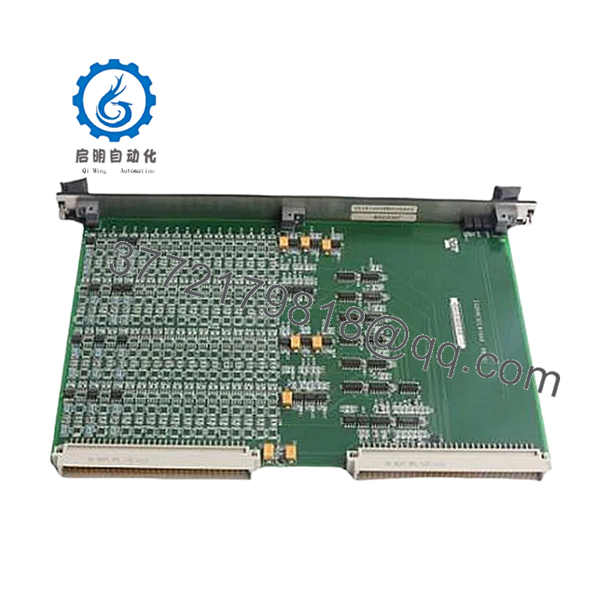
| Visual Indicators | 3 Green diagnostic front-panel LEDs |
| Manual Reference | GEI-100456 |
Product Introduction & Supply Chain Strategy
The GE IS200ESELH2AAA is a dedicated Exciter Selector (ESEL) printed circuit board built strictly for GE EX2100 and EX2100e Excitation Control Systems, often operating alongside Mark VI turbine control infrastructure. The primary role of this board is to act as a precision receiver for six logic-level gate pulse signals generated by the primary EMIO (Exciter Main I/O) module. It safely routes and amplifies these critical gate pulses across six separate cables directly to the Exciter Gate Pulse Amplifier (EGPA) boards housed in the power conversion cabinet, ensuring perfectly synchronized control over the generator’s rotor excitation field.
Maintaining this exact module as a New Surplus asset on-site is a fundamental pillar of modern Total Cost of Ownership (TCO) optimization within heavy power generation assets. Because excitation controls directly command the main generator field, an ESEL board failure results in an immediate turbine trip and costly unplanned grid disconnects. Refurbished boards present massive hidden liabilities, such as thermal breakdown within the signal-routing path or aged silicon that causes pulse-timing drift. By stocking an unblemished, conformally coated New Surplus unit, procurement managers shield their operations from unpredictable OEM manufacturing lead times and secure factory-level pulse accuracy from the exact second of installation.

- IS200ESELH2AAA
Installation & Configuration Guide
Stage 1: Pre-Installation (Prep & Safety)
- Completely de-energize the entire excitation system and apply strict lock-out/tag-out (LOTO) procedures to the power conversion cabinet feeds.
- Open the control enclosure door and verify that the master power indicators on the EPDM and EPSM power supply modules are completely dark.
- Don a high-quality, calibrated ESD wrist strap and connect its grounding clip to an unpainted metal section of the rack chassis frame.
- Verify that all three green status LEDs at the top of the existing IS200ESELH2AAA faceplate are fully off before attempting removal.
Stage 2: Removal
- Loosen the captive retaining screws located at the absolute top and bottom of the board faceplate near the extraction handles. Do not try to remove these screws completely as they are mechanically held inside the faceplate.
- Pop the upper and lower plastic ejector tabs outward simultaneously to cleanly unseat the P1 and P2 connectors from the rear VME backplane pins.
- Grip the board by the faceplate edge with both hands and pull it straight out along the enclosure track, ensuring the surface components do not contact adjacent cards. Place the old module inside an anti-static shield bag.
Stage 3: Installation (Clone & Seat)
- Remove the New Surplus IS200ESELH2AAA from its factory ESD packaging inside the clean workspace.
- Confirm the card features no jumpers or manual potentiometer adjustment points, meaning it requires no physical pre-configuration.
- Align the circuit board edges carefully with the upper and lower slots of the designated rack position.
- Slide the module backward smoothly until you feel the connectors make initial contact with the backplane.
- Use your thumbs to press firmly and evenly on the top and bottom of the faceplate simultaneously until the ejector handles lock home. Alternate between the top and bottom captive screws to pull the board squarely into final position.
Stage 4: Power-On & Testing
- Ensure all tools are accounted for, unclip your grounding wrist strap, and close the internal swinging rack doors.
- Remove your LOTO devices and restore control power feeds to the excitation enclosure.
- Observe the three front-panel green LEDs; they must cycle through their standard initialization sequence and show a steady status according to your application system layout.
- Access the C Controller terminal interface or ToolboxST diagnostics window to confirm that the active ESEL board is communicating error-free with the master EMIO module.
Firmware/Software Versions & Upgrade Notes
The GE IS200ESELH2AAA runs specialized, hardware-mapped logic arrays tailored for the EX2100 3-bridge, 100mm drive ecosystem. This card contains zero field-upgradable software components on the board itself, as processing logic is governed by the active C Controller and the upstream EMIO board.
When replacing this card, you must match the exact hardware variant groupings. The H2 identifier indicates that this specific board is conformally coated and carries three bridge drivers; replacing it with an H1 (single bridge) or H3 variant will trigger a severe configuration fault in the master controller. Always verify that your current application software parameters in the Mark VI project folder are mapped correctly for a 3-bridge configuration before restarting the excitation loop.
Frequently Asked Questions (FAQ)
Q: What is the significance of the “H2AAA” suffix in this part number?
A: The “H2” grouping tag defines this board as a conformally coated assembly equipped with exactly three bridge drivers, making it the correct match for 3-bridge 100mm excitation layouts. The trailing “AAA” code indicates that the board contains three significant, factory-implemented product revisions (Functional Revision 1, Functional Revision 2, and Artwork Revision A), all rated at the highest factory standard.
Q: Are these units truly new, or are they clean pull-downs from old power stations?
A: Every single IS200ESELH2AAA we supply is guaranteed to be New Surplus inventory. They have never been installed in an active rack, never exposed to turbine heat cycles, and have zero operational hours. These units are secured from excess warehouse reserves and maintained in static-safe packaging to preserve factory-level silicon conditions.
Q: Why does this New Surplus board cost more than a standard refurbished card?
A: The pricing represents the value of complete operational reliability. Refurbished cards are failed components that have been patched up with generic consumer-grade parts, which introduces serious risks of timing drift in your gate pulses. A minor failure on an excitation board can trip a multi-megawatt generator, causing catastrophic downtime costs. This New Surplus board provides zero-compromise reliability at a significantly lower cost than the original factory list price.
Q: Can this selector board be pulled out and swapped while the generator is running under load?
A: Absolutely not. The IS200ESELH2AAA handles real-time gate pulses that control the firing of the main power bridges. Unplugging the module while active will instantly break the feedback loop, drop the excitation field, and trigger an emergency turbine trip. Always completely de-energize and lock out the excitation system before starting work on the hardware.
Q: What type of warranty protection do you include with this GE turbine control component?
A: We provide a full 1-year commercial replacement warranty on this New Surplus board, starting from the day it leaves our warehouse door. Because all our inventory is managed under strict climate control and passes through detailed physical and visual QA inspections, we guarantee that it will drop right into your EX2100 rack and run flawlessly.


