
 WhatsApp: +86 16626708626
 Email:
  Phone: +86 16626708626
Description
3. Key Technical Specifications
| Parameter | Value |
|---|---|
| Model Number | IS200HFPAG1AEC |
| Manufacturer | General Electric |
| Product Category | High Frequency AC / Fan Power Supply Board |
| Platform | GE Speedtronic Mark VI IS200 |
| Primary Function | Converts AC/DC input to regulated outputs |
| Input Voltage Range | 230–1000 V DC |
| Output Monitoring | 17.7 VAC and 48 VAC/DC status outputs |
| LED Indicators | 2 Green LEDs |
| Fuse FU1 | 250 V / 2.5 A |
| Fuse FU2 | 250 V / 1.0 A |
| Fuse FU3 | 600 V / 2.0 A |
| Fuse FU4 | 250 V / 4.0 A |
| Connector Count | 8 output connectors + 4 stab-on inputs |
| Variable Components | 1 onboard variable resistor |
| Product Lifecycle | Obsolete |
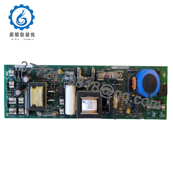
The IS200HFPAG1AEC functions as a High Frequency AC/Fan Power Supply board in the Mark VI architecture. It converts incoming AC or DC input power into regulated outputs used by connected devices and fan systems.
4. Product Introduction
GE IS200HFPAG1AEC is a High Frequency AC/Fan Power Supply board designed for the GE Speedtronic Mark VI turbine control platform. The board converts incoming high-voltage AC or DC power into regulated output voltages used for fan assemblies and related cabinet support hardware.
In field deployments of Mark VI systems, support boards like this rarely receive attention until cabinet cooling or auxiliary voltage issues begin causing intermittent faults. I have seen turbine cabinets throw unrelated alarms because support voltage degraded under load. Keep a verified spare on site if the unit supports critical generation assets.
5. Installation & Configuration Guide
Stage 1: Pre-Installation Preparation (Estimated: 10 minutes)
⚠️ Safety First: Notify operations of downtime. Verify process equipment is in a safe state. Apply lockout/tagout procedures. Remove control power and wait at least 5 minutes for capacitor discharge.
This board handles elevated DC input levels. Treat cabinet energy storage seriously.
Tools Required:
- ESD wrist strap
- PH1 screwdriver
- Fluke 115 multimeter
- Wire labels
- Smartphone camera
- ESD work mat
Data Backup
- Export cabinet configuration where applicable.
- Record all active alarms.
- Photograph wiring and connector positions.
- Photograph board labels and revision tags.
- Record fuse positions and ratings.
Stage 2: Removing the Old Module (Estimated: 5 minutes)
- Remove cabinet covers.
- Label all wiring connections.
- Disconnect stab-on connectors carefully.
- Release mounting hardware.
- Pull board straight outward.
⚠️ Do not force removal.
The board contains multiple power connections and aging plastic connectors. I’ve seen cracked connector bodies create a larger outage than the original failure.
⚠️ Keep the old board until the replacement runs successfully.
Stage 3: Installing the New Module (Estimated: 10 minutes)
- Connect ESD protection first.
- Verify exact part number: IS200HFPAG1AEC
- Configuration Clone (Crucial): Verify fuse values and connector orientation before installation.
- Insert board carefully and confirm full seating.
- Reconnect all wiring.
Self-Checklist:
- Correct model verified
- Connector placement confirmed
- Wiring secured
- Mounting hardware secured
- ESD procedures followed
⚠️ This is the most common rookie mistake, but it happens constantly. Take a picture before you pull it. I can’t stress this enough.
Stage 4: Power-On & Testing (Estimated: 10 minutes)
Pre-Power Check
Verify no short exists across supply rails using a Fluke meter.
Power sequence:
- Apply rack power only.
- Observe both green LEDs.
- Verify 17 V OK indication.
- Verify 48 V OK indication.
- Check fan and output operation.
The board uses dedicated LED indicators for 17.7 VAC and 48 VAC/DC output status. Missing indication often points directly toward fuse faults.
⚠️ Troubleshooting Note: If the 48 V OK LED remains off, inspect FU1 first. If 17 V OK remains off, inspect FU4 before replacing the board.
Technical Pitfall & Survival Guide
❗ Firmware Revision Mismatch
Issue: Mark VI cabinets occasionally react differently to hardware revision changes.
Avoidance: Record all board revision information before replacement.
I’ve seen maintenance teams spend two days troubleshooting a communication issue that turned out to be a revision mismatch.
❗ DIP Switch / Jumper Misconfiguration
Issue: Default settings may differ from plant configuration.
Avoidance: Photograph every jumper and configuration point.
Take a picture before removal. Every time.
❗ Terminal Block / Wiring Incompatibility
Issue: Similar board suffixes sometimes route connectors differently.
Avoidance: Verify documentation and compare physical layouts.
Never wire from memory.
❗ Power Draw Specifications
Issue: Additional board loads can exceed available cabinet power margin.
Avoidance: Maintain 20% reserve capacity.
Cabinets accumulate load over years. A few extra modules can quietly push supplies beyond acceptable margins.
❗ Electrostatic Discharge (ESD)
Issue: Damage before installation.
Avoidance: Wear grounded wrist straps and use ESD surfaces.
I watched an engineer unpack a replacement board during winter without protection. Powered on. Immediate smoke. Expensive lesson.
Keep these checks in mind and you’ll save yourself 90% of typical rework time.
- IS200HFPAG1AEC
6. Frequently Asked Questions (FAQ)
Q1: Can I hot-swap this module?
No.
Power supply hardware in Mark VI cabinets should not be removed under power. Live extraction can damage connectors and create transient faults.
Q2: Is GE IS200HFPAG1AEC obsolete?
Yes.
The board belongs to GE’s legacy Speedtronic Mark VI platform. Current inventory generally comes from surplus and refurbished channels.
Q3: Is this genuinely new?
Usually “New Original” means unused surplus inventory.
Factory packaging often varies because inventory may have remained in controlled storage for years. Request photographs and serial verification.
Q4: Will I lose programming logic during replacement?
No.
This is a power supply board, not a processor or control CPU. Controller logic resides elsewhere in the Mark VI architecture.
Q5: Why is pricing lower than historical GE OEM pricing?
OEM production ended years ago.
Current market pricing depends on condition, testing history, and inventory availability. New-surplus listings and refurbished stock vary considerably. Recent market listings show surplus inventory still available.
Q6: How do you test surplus inventory?
Our SOP follows documented engineering procedures:
- OEM source verification and customs traceability review
- Anti-counterfeit checks and serial verification
- Visual inspection for corrosion, rework marks, and UV yellowing
- Functional testing on compatible GE test hardware
- Communication and load verification
- 500 V Megger insulation test (>10 MΩ)
- Hardware revision documentation
- QC sign-off and ESD packaging
We use Fluke meters and genuine GE-compatible racks where available.
Test videos and inspection photos are available upon request.
Q7: What should I check first if output power is missing?
Start with the LEDs and fuse values.
The board has four onboard fuses and dedicated output status indicators. I have watched technicians replace healthy boards while a failed fuse sat in plain sight. Start with basics. Verify voltage. Verify fuses. Then move deeper.


