
 WhatsApp: +86 16626708626
 Email:
  Phone: +86 16626708626
Description
3. Key Technical Specifications
| Parameter | Value / Specification |
| Manufacturer | General Electric (GE) |
| Part Number | IS200JPDBG1A |
| Series Compatibility | Mark VI Speedtronic |
| Module Integration | Part of the IS2020JPDB AC PDM Module |
| Input Voltage Rating | 115 VAC or 230 VAC nominal (50/60 Hz) |
| Maximum Current Rating | 20 A |
| Output Capabilities | Bulk 28 VDC control power supplies |
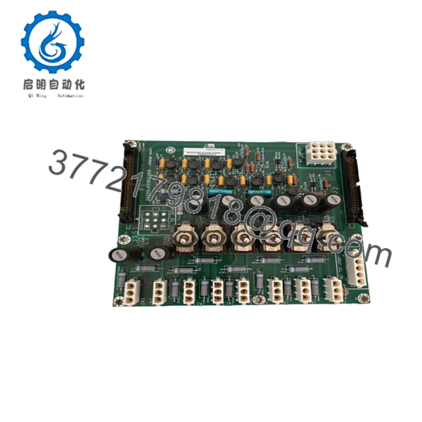
| Circuit Protection | 8 onboard fuses with passive monitoring circuits |
| Switch Integration | 6 dedicated on/off toggle switches |
| Connectors | 2 Ribbon cable headers |
| Environmental Compliance | Meets EN50178 (Elevation/Humidity) and IEC 529 (Dust protection) |
| Operating Humidity | 5% to 95% Non-condensing |
4. Product Introduction & Supply Chain Strategy
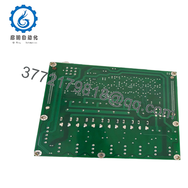
The GE IS200JPDBG1A is the primary AC power distribution board engineered for the Mark VI Speedtronic turbine control platform. Serving as the foundation of the IS2020JPDB AC power module, this board processes input line utility voltages of 115/230 VAC at up to 20 A, supplying stable bulk 28 VDC power to control processors and I/O packs. It incorporates passive diagnostic monitoring circuitry across all fused pathways to transmit real-time AC voltage magnitudes and circuit status signals back to the central controller via dual integrated ribbon connectors.
Carrying this specific module as a New Surplus asset directly optimizes your plant’s Total Cost of Ownership (TCO). Since power distribution boards operate as a single point of failure for downstream I/O racks, any component degradation introduces severe lead time variability and risk of complete control system blackout. Refurbished power cards are highly unreliable due to latent thermal fatigue in their onboard copper traces, capacitors, and toggle mechanisms. Investing in uninstalled, factory-sealed surplus inventory eliminates these functional anomalies, providing immediate plug-and-play field reliability during critical infrastructure emergencies.
- IS200JPDBG1A

- IS200JPDBG1A
5. Installation & Configuration Guide
Stage 1: Pre-Installation (Prep & Safety)
- Execute mandatory lock-out/tag-out (LOTO) protocols on the primary AC power mains feeding the PDM assembly cabinet.
- Confirm that the input line reads zero voltage using a calibrated industrial digital multimeter before opening access shields.
- Fasten a grounded ESD wrist strap to your arm and clamp it to the clean metal framework of the enclosure enclosure.
- Record or take a clear photograph of all six toggle switch positions (ON/OFF) and match the ratings of all eight physical fuses.
Stage 2: Removal
- Disconnect the 9-position main AC input plug along with the auxiliary 3-position and 5-position plug connections from the board face.
- Carefully unplug the dual data ribbon cables by evenly applying pressure to the side ejector tabs.
- Unscrew the mechanical retaining fasteners locking the board chassis assembly into the sub-rack frame, and withdraw the card smoothly away from its guide slot tracking.
Stage 3: Installation (Clone & Seat)
- Unbox the new surplus IS200JPDBG1A board within an ESD-controlled environment.
- Verify all eight fuses match the specific OEM current ratings of the card being replaced, and adjust the six toggle switches to mirror the original positions exactly.
- Align the power board with the rack enclosure frame guide rails, sliding it forward smoothly until it is seated firmly. Secure all structural retaining screws back into place.
Stage 4: Power-On & Testing
- Re-terminate all ten plug connectors and click the dual monitoring ribbon cables securely back into their headers.
- Re-energize the incoming primary AC line breaker to power up the module.
- Observe the passive monitoring feedback signals at the HMI workstation and verify that the bulk 28 VDC rails are stable and free of voltage sag alerts.
6. Firmware/Software Versions & Upgrade Notes
The IS200JPDBG1A operates purely via discrete hardware components, passive voltage sensors, and electromechanical circuitry, meaning it contains no flash memory or programmable firmware arrays. The “G1A” functional grouping indicates the specific baseline revision layout of the board’s traces and voltage attenuation levels.
⚠️ CRITICAL WARNING: When replacing this board, you must verify the component suffix compatibility. Interchanging this board with non-A revision variants within a shared or parallel Power Distribution Pack can result in misaligned voltage monitoring tolerances. This causes the PPDA diagnostic engine to flag false overcurrent or phase imbalance conditions, resulting in unnecessary, preventative turbine trips.
7. Frequently Asked Questions (FAQ)
- What makes this New Surplus board a safer choice than a cheaper refurbished power distribution module?
Power distribution modules carry continuous high currents and experience intense ambient thermal stress. Refurbished units frequently contain aged toggle switches, fatigue-weakened trace joints, or degraded capacitors that look clean but fail prematurely under load. Sourcing a New Surplus card provides zero-hour components and factory-level electrical insulation reliability, preventing the immense financial impact of an unexpected plant shutdown.
- What are the functions of the six onboard toggle switches?
The six toggle switches provide isolated, manual on/off control for specific branches within the AC power distribution circuit, allowing maintenance teams to safely cut power to targeted downstream equipment during servicing without de-energizing the entire control engine.
- Can this power distribution card be hot-swapped while the turbine control system is online?
No. Splicing or disconnecting a major power distribution hub like the IS200JPDBG1A while energized creates severe electrical arcing risks and will abruptly drop power to connected processing racks. This drops downstream outputs instantly and forces an immediate emergency trip. Always execute a complete power isolation before removal.
- How does the system monitor the health of the onboard fuses?
The board features integrated passive monitoring circuitry connected to each fuse channel. These sensors constantly read the voltage drop across the fuses and transmit phase magnitude data back to the controller through the dual ribbon cables, triggering immediate system alerts if a fuse blows.
- What type of warranty coverage does this New Surplus board include?
This original New Surplus module includes a comprehensive 1-year warranty from the date of purchase, providing complete protection that satisfies your operational reliability requirements.


