
 WhatsApp: +86 16626708626
 Email:
  Phone: +86 16626708626
Description
3. Key Technical Specifications
| Parameter | Value |
|---|---|
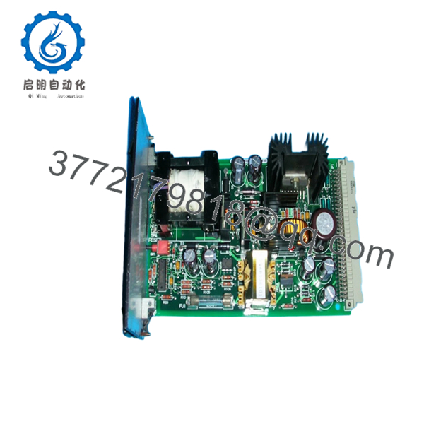
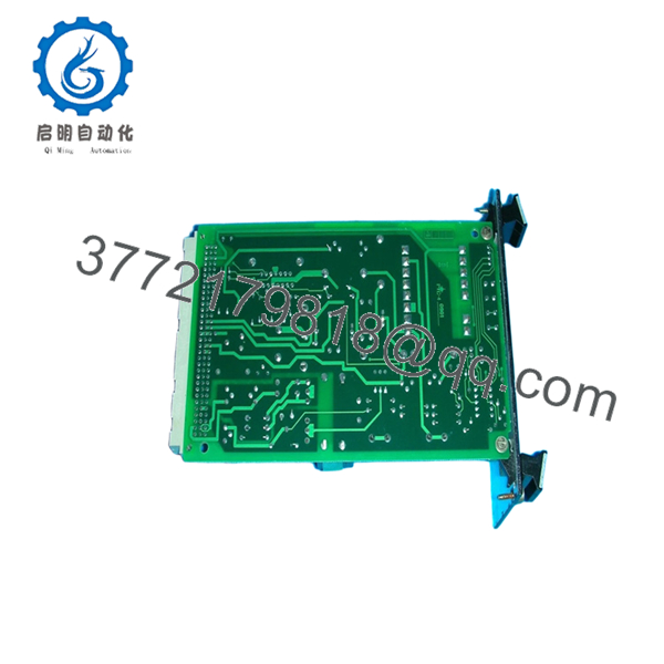
| Part Number | IS200RAPAG1BBA |
| Manufacturer | General Electric |
| Product Type | Rack Power Supply Board |
| Functional Acronym | RAPA |
| Series | Speedtronic Mark VI IS200 |
| Primary Function | Rack DC voltage generation and reset handling |
| Input Voltage | 48 V square-wave input |
| Input Frequency | 25 kHz |
| Output Voltage 1 | ±18–24 V DC unregulated, 400 mA max |
| Output Voltage 2 | ±15 V DC regulated ±5%, 1.0 A max |
| Output Voltage 3 | ±5 V DC regulated ±5%, 7.0 A max |
| 24COM Referenced Output | ±24 V DC unregulated, 1.5 A max |
| Test Points | 4 onboard test points |
| Indicators | 2 status LEDs |
| Protection | Single onboard fuse |
| Adjustable Hardware | Reset switch |
| Memory Device | Serial 1024-bit ID memory chip |
| Mounting Style | Innovation Series rack-mounted PCB |
| Cooling Method | Passive cabinet airflow |
| Condition Options | New Surplus / Refurbished Tested |
| Availability | Limited global surplus inventory |
Technical references identify the IS200RAPAG1BBA as a GE Mark VI Rack Power Supply Board used to provide DC control voltages and master reset functionality inside Innovation Series racks.
4. Product Introduction
The GE IS200RAPAG1BBA is a Rack Power Supply Board designed for GE Speedtronic Mark VI turbine control systems. The board installs into the Innovation Series rack architecture and supplies regulated DC control voltages for adjacent control modules, communication boards, and interface assemblies.
In field deployments of Mark VI systems, the RAPA board is one of the first modules engineers inspect when multiple rack communication faults appear simultaneously. A weak +5 V rail or unstable reset signal can create intermittent diagnostics that look like processor or backplane failures when the actual issue is power distribution instability.
5. Installation & Configuration Guide
Stage 1: Pre-Installation Preparation (Estimated Time: 10 Minutes)
⚠️ Safety First
- Notify operations and place the turbine or drive system into a verified shutdown condition.
- Lock out and tag out all cabinet power sources.
- Wait at least 5 minutes for DC-link and rack capacitors to discharge fully.
❗ I’ve watched engineers trust cabinet indicator lamps instead of measuring actual DC bus voltage. One residual charge incident is enough to make you stop doing that permanently.
Tools Required
- Grounded ESD wrist strap
- PH1 screwdriver
- Fluke 115 multimeter
- Wire labels
- Smartphone for documentation photos
- Flashlight for connector inspection
Data Backup
- Export current Mark VI configuration backups.
- Photograph:
- Rack slot position
- Connector orientation
- Cable routing
- Adjacent module locations
- Record:
- Firmware revisions
- Cabinet labels
- Existing fault history
⚠️ The IS200RAPAG1BBA may look nearly identical to adjacent Mark VI boards during outage pressure. Verify the full suffix before removal.
Stage 2: Removing the Old Module (Estimated Time: 5 Minutes)
- Remove cabinet access covers carefully.
- Label all ribbon cables and interface wiring.
- Disconnect connectors evenly without flexing the PCB.
- Release rack retention tabs or mounting hardware.
- Pull the board straight outward from the rack guides.
- Inspect:
- P1 backplane connector
- Bent pins
- Dust accumulation
- Heat discoloration near power components
- Fuse condition
⚠️ Note: Keep the original board available until the replacement passes full operational testing.
I’ve seen plants scrap the original module too early, only to discover the actual problem was a damaged backplane connector.
Stage 3: Installing the New Module (Estimated Time: 10 Minutes)
- Wear the grounded ESD strap before touching the replacement board.
- Verify exact model:
- IS200RAPAG1BBA
- Inspect the replacement PCB for:
- Rework marks
- Corrosion
- Cracked solder joints
- Damaged heat sinks
- Configuration Clone (Crucial):
- Verify board revision compatibility
- Confirm jumper and switch settings if applicable
- Inspect reset switch condition
- Insert the board carefully into the Innovation Series rack guides.
- Press evenly until fully seated into the P1 backplane connector.
- Tighten mounting hardware securely.
- Reconnect all cables and verify routing clearance.
Self-Checklist
- Board revision verified
- P1 connector seated fully
- Mounting tabs secured
- No bent pins
- No loose hardware inside cabinet
❗ A partially seated RAPA board can generate intermittent rack resets that waste hours of troubleshooting. Push evenly and verify full engagement.
Stage 4: Power-On & Testing (Estimated Time: 10–15 Minutes)
Pre-Power Check
- Verify no shorts exist on the DC control rails.
- Confirm cabinet grounding continuity.
- Inspect all backplane connectors visually.
Power-On Steps
- Energize the control rack only.
- Observe startup LED indicators:
- IPOK and MPOK LEDs should stabilize normally
- Measure output rails using onboard test points:
- +5 V DC
- ±15 V DC
- DCOM
- Connect the engineering workstation.
- Verify:
- Rack communication
- Stable processor operation
- No spontaneous resets
- Reload configuration files if required.
- Perform dry-run testing before enabling field outputs.
⚠️ Troubleshooting Note
- Repeated rack resets usually indicate:
- Weak +5 V regulation
- Backplane seating issues
- Fuse degradation
- Overloaded power rail
I’ve personally seen a Mark VI startup delayed nearly 18 hours because a replacement RAPA board revision delivered unstable voltage under thermal load after about 20 minutes of runtime.
- IS200RAPAG1BBA
- IS200RAPAG1BBA
6. Frequently Asked Questions (FAQ)
Q1: Can I hot-swap the IS200RAPAG1BBA under power?
No. Do not hot-swap this board.
The RAPA board distributes rack control voltages and reset functions. Pulling it under power can crash the entire Mark VI rack and potentially damage adjacent modules.
GE documentation specifically warns against removal while energized.
Q2: What does the IS200RAPAG1BBA actually do?
The board provides regulated DC control voltages for other Mark VI rack modules and handles rack reset functionality through the P1 connector. It also supplies monitoring test points and status diagnostics.
Q3: Is this module obsolete?
Yes. The IS200RAPAG1BBA is obsolete from the OEM production standpoint.
Most available inventory today comes from:
- New surplus stock
- Plant spare inventory
- Refurbished tested assemblies
Plants still operating Mark VI systems continue purchasing these boards for outage spares and lifecycle extension programs.
Q4: What is the most common installation mistake with this board?
❗ Installing the wrong RAPA revision.
GE produced multiple RAPA variants including:
- G1A
- G1B
- Different revision suffixes
Some revisions share physical dimensions but provide different DC output characteristics. Always verify the complete part number and revision suffix before installation.
Q5: Why are there four onboard test points?
The onboard test points allow direct measurement of critical power rails during troubleshooting:
- +5 V DC
- ±15 V DC
- Digital common
This is extremely useful during intermittent reset or communication fault diagnostics.
Q6: Why is surplus pricing lower than historical OEM pricing?
Because GE no longer manufactures many Mark VI boards through standard production channels.
Pricing now depends on:
- Remaining inventory worldwide
- Outage demand
- Condition
- Warranty coverage
- Electrical test quality
Lower price alone does not mean counterfeit hardware, but serious suppliers should provide:
- Actual board photos
- Voltage test reports
- Burn-in documentation
- Serial verification
Q7: What QC process should a supplier perform before shipment?
Minimum acceptable testing should include:
- Visual inspection under magnification
- Serial and revision verification
- 500 V insulation resistance testing (>10 MΩ)
- Ground continuity verification
- Full DC rail measurement under load
- Rack startup simulation
- 24-hour thermal burn-in testing
- ESD-safe anti-static packaging
Good suppliers normally test these boards on genuine GE Innovation Series racks and can provide startup videos or test photos upon request.
Keep these checks in mind and you’ll avoid most field replacement headaches.


