
 WhatsApp: +86 16626708626
 Email:
  Phone: +86 16626708626
Description
Key Technical Specifications
| Parameter | Value |
| Functional Acronym | TBAI |
| Number of Inputs | 10 Channels (Supports 2-, 3-, 4-wire, or externally powered) |
| Number of Outputs | 2 Channels (Jumper configurable for 0-20 mA or 0-200 mA) |
| Input Signal Range | \pm5 V DC, \pm10 V DC, or 4-20 mA |
| Transducer Power | +24 V DC current-limited supply per input |
| Power Consumption | Less than 31 W |
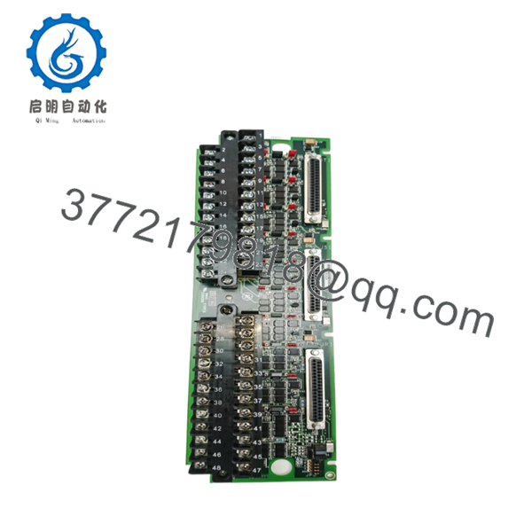
| Connector Interface | 3 \times 37-pin D-sub connectors (JR1, JS1, JT1) |
| Terminal Blocks | Two barrier blocks (TB1, TB2) with 24 terminals each (#12 AWG max) |
| Application Profile | Simplex or Triple Modular Redundant (TMR) architectures |
| Operating Temperature | −30 to +65°C |
Product Introduction & Supply Chain Strategy
The GE IS200TBAIH1B is an Analog Input Terminal Board engineered for the Mark VI Speedtronic turbine control system. It acts as the primary interface for field wiring, accepting 10 analog inputs from temperature, pressure, or position transmitters, and managing two analog control outputs. The board distributes signals to either a single I/O processor board (Simplex) or fans them across three independent processors (R, S, and T) for Triple Modular Redundant configurations in mission-critical power generation environments.
Procuring this module as New Surplus provides a strategic defensive reserve against unexpected capital asset downtime. Because the Mark VI legacy ecosystem is mature, relying on used components introduces unacceptable operational risks due to capacitor drying and contact degradation. Acquiring factory-sealed surplus components reduces the Total Cost of Ownership (TCO) compared to OEM list prices while protecting the facility from stock-out incidents that can interrupt power production.

- IS200TBAIH1B
Installation & Configuration Guide
Stage 1: Pre-Installation (Prep & Safety)
- Isolate all active power distribution circuits connected to the turbine control panel using approved lock-out/tag-out procedures.
- Put on a grounded, static-dissipative wrist strap and attach the clip to the bare metal framework of the control cabinet.
- Document the existing wiring configurations on terminal blocks TB1 and TB2, noting the exact position of all shields.
- Photograph the positions of all onboard red hardware jumpers to guarantee an exact configuration clone.
Stage 2: Removal
- Loosen the terminal retention screws on TB1 and TB2, gently lifting the field wiring bundles away from the circuit card assembly.
- Disconnect the 37-pin D-sub cables from the ports labeled JR1, JS1, and JT1 on the right edge of the unit.
- Remove the mounting hardware securing the board to the panel backplane assembly.
- Extract the card straight out to prevent scraping, twisting, or bending the rear terminal trace pathways.
Stage 3: Installation (Clone & Seat)
- Verify the hardware jumpers on the new surplus IS200TBAIH1B match the old board precisely to set the correct input spans (\pm5 V, \pm10 V, or 4-20 mA).
- Align the board with the cabinet mounting pillars and fasten the chassis screws firmly.
- Reattach the 37-pin D-sub cables to connectors JR1, JS1, and JT1, securing the retaining thumb screws.
- Terminate the field wiring back onto TB1 and TB2 using the documented torque ratings to prevent terminal resistance spikes.
Stage 4: Power-On & Testing
- Use a digital multimeter to verify that the 24 V DC power bus exhibits no direct ground faults or short circuits.
- Re-energize the master control enclosure panel supply breakers.
- Monitor the status indicators on the companion VAIC processor module to ensure a successful initialization handshake.
- Check the control system diagnostic logs to confirm that all analog loop inputs register active current values without signaling card faults.
Firmware/Software Versions & Upgrade Notes
⚠️ CRITICAL REVISION NOTICE: The IS200TBAIH1B belongs to the “B” revision architecture of the TBAI platform. This module is designed for hardware compatibility with legacy VAIC analog processor boards running early runtime configurations.
Upgrading a terminal board variant during a field replacement introduces direct hardware mismatch risks. For instance, the newer “H1C” variant requires later “D” revision VAIC modules. Forcing cross-generation pairings without evaluating the overall cabinet hardware profile can result in processing timeouts or calibration errors during signal conversion. Always maintain identical hardware revision levels to ensure backward compatibility without modifying the baseline control application code.
Frequently Asked Questions (FAQ)
Why is this New Surplus board priced higher than a refurbished option?
Our inventory is strictly New Surplus hardware, meaning it has zero operating hours and has never undergone component-level soldering or modifications. Refurbished parts often carry degraded capacitors hidden beneath cosmetic cleaning. Spending a small premium for a new unit eliminates the threat of premature failure, saving your facility from unplanned downtime incidents that exceed the component cost by orders of magnitude.
How do I know this IS200TBAIH1B is truly an unenergized unit?
Every single board undergoes strict quality control checks at our intake station. We verify factory serial sequences, inspect the backplane pins for zero insertion wear, and ensure the module arrives in ESD-safe protective packaging. Full serial number traceability reports are available for engineering review.
Does this board support both Simplex and TMR configurations?
Yes. The board features three separate D-sub connectors (JR1, JS1, JT1). In a Simplex installation, only a single cable connects the unit to the processor. For Triple Modular Redundant (TMR) operations, signals are fanned out to all three connections simultaneously to achieve fault-tolerant processing.
Can I hot-swap this terminal board while the turbine is running?
No. Replacing an analog input terminal board requires disconnecting active field wiring loops and control processors. Removing terminal connections under power will disrupt critical transducer loops, drop active signals, and trigger a master turbine trip sequence.
What is the specific function of the onboard jumpers?
The parallel rows of red jumpers configure each individual analog channel to accept either voltage (\pm5 V DC / \pm10 V DC) or current loop (4-20 mA) signals. They must be mirrored exactly from your decommissioned card to prevent incorrect signal scaling or hardware overcurrent.
What warranty terms cover this legacy component?
To match our commitment to capital efficiency and reliability, this New Surplus module comes backed by a comprehensive 1-year warranty. This extended protection window surpasses standard asset lifecycles found with used alternatives.


