
 WhatsApp: +86 16626708626
 Email:
  Phone: +86 16626708626
Description
3. Key Technical Specifications
| Parameter | Value |
|---|---|
| Manufacturer | GE (General Electric) |
| Model Number | IS200TBCIH2BCE |
| Product Type | Contact Input Terminal Board |
| Control Platform | GE Mark VIe |
| Function | Contact input interface with group isolation |
| Input Channels | 24 dry contact inputs |
| Input Voltage | 24 VDC nominal |
| Input Type | Dry contact signals |
| I/O Pack Compatibility | GE Mark VIe contact input I/O packs |
| Configuration Type | Simplex / Dual / TMR applications |
| Terminal Connection | Barrier-type terminal blocks |
| Noise Protection | Input surge and high-frequency noise suppression |
| Diagnostics | Contact input monitoring and board identification |
| Operating Temperature | Approximately -30 °C to +65 °C |
| Mounting Method | Control cabinet panel mounting |
| Replacement Class | Mark VIe terminal board assembly |
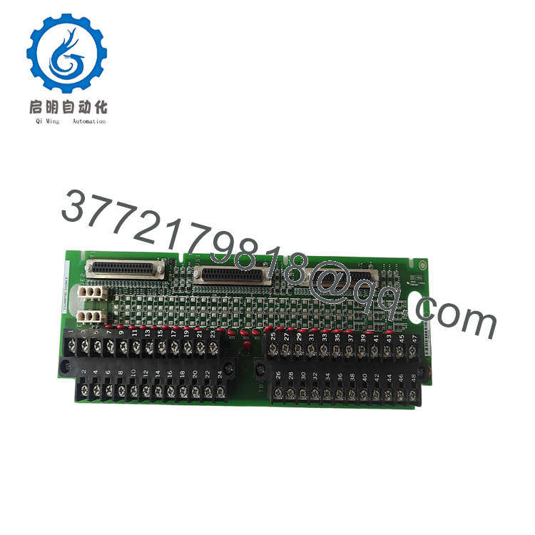
The GE IS200TBCIH2BCE is a Mark VIe Contact Input Terminal Board designed to interface 24 dry contact field signals with GE turbine control systems. The board provides field termination, signal conditioning, and connection between field devices and Mark VIe I/O packs.
4. Product Introduction
The GE IS200TBCIH2BCE is a Contact Input Terminal Board used in GE Mark VIe turbine control systems. It accepts 24 dry contact inputs from field devices such as switches, relays, and protective interlocks, then transfers these signals through compatible GE I/O packs into the turbine control architecture.
This terminal board is commonly maintained in gas turbine, steam turbine, and generator control installations where existing Mark VIe hardware remains in service. Replacement requires verification of I/O pack compatibility, terminal wiring, board revision, and cabinet configuration before installation.
5. Installation & Configuration Guide
Stage 1: Pre-Installation Preparation (15 Minutes)
⚠️ Safety First
- Notify operations personnel before starting maintenance.
- Confirm the turbine control system is in a safe maintenance state.
- Apply Lockout/Tagout (LOTO) procedures.
- Remove cabinet power.
- Wait at least 5 minutes for stored electrical energy discharge.
Tools Required
- ESD wrist strap
- PH1 screwdriver
- Fluke 115 multimeter
- Wire labels
- Smartphone for wiring photographs
- Laptop with GE ToolboxST
Data Backup
Before removing the existing board:
- Export the Mark VIe configuration.
- Record the I/O pack identification.
- Photograph all terminal wiring.
- Document field signal assignments.
- Record board serial number and revision.
- Save current ToolboxST project files.
Stage 2: Removing the Old Module (10 Minutes)
- Remove the control cabinet front cover.
- Verify power isolation.
- Remove the terminal board cover if installed.
- Label every field wire.
- Disconnect wiring carefully without forcing terminals.
- Release mounting hardware.
- Remove the board straight to protect connectors.
Inspect:
- Terminal blocks
- Board connectors
- Backplane/interface connections
- Signs of corrosion or overheating
⚠️ Keep the original IS200TBCIH2BCE installed until the replacement has completed full system testing.
Stage 3: Installing the New Module (15 Minutes)
- Wear an ESD wrist strap before handling the replacement board.
- Verify the exact catalog number:
GE IS200TBCIH2BCE
- Compare:
- Board revision
- Connector layout
- Terminal arrangement
- I/O pack compatibility
- Clone the original installation:
- Match terminal wiring exactly.
- Confirm I/O pack location.
- Verify field excitation wiring.
- Insert and secure the board.
- Tighten terminals using appropriate torque.
Installation Checklist
- Model number verified
- Terminal wiring matched
- I/O pack connection confirmed
- Mounting hardware secured
Stage 4: Power-On & Testing (30 Minutes)
Pre-Power Check
Use a multimeter to verify:
- No short circuits on control power
- Correct 24 VDC supply
- Proper grounding continuity
- Correct field wiring polarity
Power-On Steps
- Power up the control rack only.
- Observe I/O pack status LEDs.
- Connect GE ToolboxST.
- Verify hardware identification.
- Confirm firmware and configuration compatibility.
- Simulate contact inputs.
- Verify all input points change state correctly.
⚠️ Troubleshooting Note
- Communication fault: Check I/O pack connection and terminal board identification.
- Incorrect input status: Verify field wiring and contact wetting voltage.
- Hardware mismatch alarm: Confirm terminal board revision matches the Mark VIe configuration.
-

- IS200TBCIH2BCE
- IS200TBCIH2BCE
SOP Quality Verification
1. Inbound Inspection & Traceability
Inspection procedure:
- Verify OEM label and serial number.
- Confirm source documentation.
- Perform anti-counterfeit checks.
- Inspect PCB condition.
Visual inspection:
- No corrosion
- No scratches
- No repair marks
- No UV yellowing
- Connector pins clean and undamaged
Accessory audit:
- Manuals where supplied
- Factory documents where available
- Warranty records
2. Live Functional Testing
Testing should be performed using a genuine GE Mark VIe test rack with compatible contact input I/O pack.
Verification steps:
- Power-on self-test
- Board identification check
- I/O pack communication handshake
- 24-channel contact simulation
- Input state verification
- Alarm/status monitoring
- Continuous operation exceeding 24 hours
- Thermal monitoring
An official Test Report should be generated.
Test photographs and videos should be available upon request.
3. Electrical Parameter Testing
Required checks:
- 500 V Megger insulation resistance test (>10 MΩ where applicable)
- Ground continuity test
- 24 VDC input verification
- Terminal contact inspection
4. Firmware & Configuration Verification
Document:
- Board hardware revision
- I/O pack model
- Mark VIe configuration compatibility
- Terminal assignments
Backup:
- ToolboxST project
- Wiring photos
- Cabinet location records
5. Final QC & Packaging
Final preparation:
- QC inspector sign-off
- Anti-static ESD bagging
- Bubble wrap protection
- Heavy-duty corrugated boxing
- QC Passed label with inspection date
Technical Pitfalls & Survival Guide
❗ I/O Pack Compatibility Mismatch
The terminal board and I/O pack must match.
I have seen replacement projects delayed because the terminal board was physically correct but configured for a different Mark VIe I/O arrangement.
Always verify the installed I/O pack model before ordering.
❗ Terminal Wiring Errors
This is the most common field mistake.
Take clear photos before removing the old board. A single misplaced contact input wire can create false alarms or disable protection logic.
Never reconnect from memory.
❗ Contact Wetting Voltage Issues
Dry contact inputs require correct excitation voltage.
If the contact wetting supply is missing or incorrect, the board may appear healthy while all field inputs remain inactive.
Verify:
- 24 VDC supply
- Contact source wiring
- Input common connections
❗ Board Revision Differences
GE Mark VIe hardware revisions may look similar but have different compatibility requirements.
Record the original revision before replacement and verify against the OEM hardware documentation.
❗ Electrostatic Discharge (ESD)
The terminal board contains sensitive interface circuitry.
Always:
- Wear a grounded wrist strap.
- Use an ESD mat.
- Handle boards by the edges.
Keep these checks in mind and you’ll save yourself significant rework time during GE Mark VIe I/O replacement.
6. Frequently Asked Questions (FAQ)
Q1. What is the GE IS200TBCIH2BCE used for?
The IS200TBCIH2BCE is a GE Mark VIe Contact Input Terminal Board used to connect 24 dry contact field signals to turbine control I/O hardware.
Q2. Is the IS200TBCIH2BCE still manufactured?
The IS200TBCIH2BCE is considered a legacy Mark VIe component. Availability is generally through New Original (New Surplus) inventory or Refurbished (tested) stock.
Q3. Can I hot-swap this terminal board?
No.
For most GE Mark VIe installations, remove power before replacing terminal boards. Working under power can damage connectors or create false control signals.
Q4. Will replacing this board erase my turbine control logic?
No.
The terminal board does not contain the complete Mark VIe application logic. However, always back up the ToolboxST project before maintenance work.
Q5. What is the direct replacement if this model is unavailable?
The replacement depends on the installed I/O pack, Mark VIe configuration, and hardware revision. Verify the exact terminal board and I/O pack combination using GE documentation before selecting an alternative.
Q6. Why is aftermarket pricing lower than OEM pricing?
Legacy automation hardware often comes from surplus inventory, system upgrades, and lifecycle support channels.
Before purchase, verify:
- Condition: New Original (New Surplus) or Refurbished (tested)
- Serial traceability
- Functional test records
- Warranty terms
Q7. What testing should I request before shipment?
For turbine control applications, request:
- Serial number verification
- Visual inspection report
- Mark VIe rack test results
- 24-channel input simulation results
- 24-hour operational test record
- Configuration documentation
- ESD-safe packaging confirmation
These records help reduce commissioning delays when maintaining GE Mark VIe turbine control systems.



