
 WhatsApp: +86 16626708626
 Email:
  Phone: +86 16626708626
Description
3. Key Technical Specifications
| Parameter | Value |
| Manufacturer | General Electric (GE) |
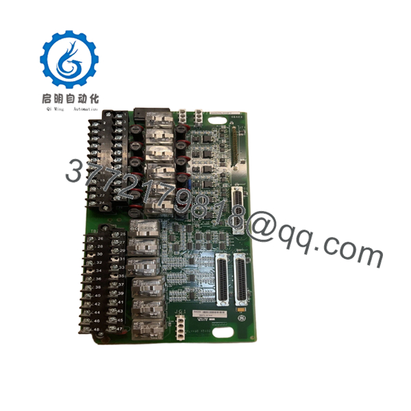
| Part Number | IS200TRLYH1BFD |
| Functional Acronym | TRLY |
| Revision Level | H1BFD |
| System Compatibility | Mark VI Speedtronic Control Systems |
| Relay Channels | 12 independent Form-C (SPDT) relays |
| Contact Max Voltage | 125 V DC / 250 V AC |
| Continuous Current Rating | 5.0 A per channel |
| Termination Blocks | Two heavy-duty, fixed barrier-type screw terminal strips |
| Cable Interface | Dual multi-pin D-type connectors for I/O processor linking |
| Operating Temperature | 0 to 60 °C (32 to 140 °F) |
| Conformal Coating | Standard across entire PCB assembly |
4. Product Introduction & Supply Chain Strategy
The GE IS200TRLYH1BFD is a Relay Terminal Board (TRLY) developed for the Mark VI Speedtronic turbine control platform. Functioning as a high-density, field-termination interface, this board provides 12 independent Form-C (Single Pole Double Throw) relay circuits used to actuate external solenoids, motor starters, and critical interlock loops. It establishes robust galvanic isolation between low-voltage digital control processors and high-power field devices, containing dual barrier-type terminal blocks designed to securely retain heavy-gauge field wiring.
Sourcing this module as a New Surplus asset represents a critical risk-management decision for infrastructure operators using legacy Mark VI systems. Because this series has reached complete manufacturer obsolescence, procurement lead time variability can introduce severe vulnerabilities to a plant’s availability metrics. Opting for a certified New Surplus board completely removes the failure vectors that plague unverified refurbished or repaired units, such as high contact-resistance across aged relay points, degraded mechanical springs, or microscopic PCB cracking from previous thermal stress events.

- IS200TRLYH1BFD
5. Installation & Configuration Guide
Stage 1: Pre-Installation (Prep & Safety)
Perform a full lock-out/tag-out (LOTO) protocol on the primary turbine control cabinet and all external power loops feeding the relay contacts. Fasten an ESD grounded wrist strap to your arm, ensuring the terminal clip is secured to an unpainted surface of the metal cabinet frame. Use a camera to document the exact wiring sequence on the barrier terminal blocks, carefully noting the wire markers for common (C), normally open (NO), and normally closed (NC) points.
Stage 2: Removal
Using a calibrated screwdriver, systematically loosen the terminal screws and remove all field wiring leads from the barrier strips. Unplug the D-sub communication cables that connect the TRLY board to the main I/O processor rack. Back out the structural screws securing the PCB to the cabinet subpanel backplate. Carefully lift the board away from its mounting footprint, ensuring no friction damage occurs to adjacent terminal structures, and seal it in an anti-static bag.
Stage 3: Installation (Clone & Seat)
Verify that the replacement IS200TRLYH1BFD precisely matches the configuration and physical profile of the removed board. Mount the new PCB directly onto the cabinet subpanel standoffs, uniforming torque on all mounting screws to ensure proper grounding contact through the board’s chassis points. Reattach the field wiring leads to their identical screw terminal positions as documented in Stage 1, then secure the multi-pin D-sub processor cables.
Stage 4: Power-On & Testing
Conduct a point-to-point resistance check on the field terminals to confirm that no short circuits were introduced during the installation process. Re-energize the auxiliary control circuits. Force an execution command from the engineering workstation to cycle each of the 12 relay channels sequentially; verify that the onboard mechanical contacts pick up reliably, the status LEDs toggle correctly, and no diagnostic fault strings populate the master control terminal.
6. Firmware/Software Versions & Upgrade Notes
The IS200TRLYH1BFD operates as a passive mechanical and electrical termination assembly and does not contain user-flashable microprocessor firmware blocks. Its onboard diagnostic circuits and relay tracking paths are completely controlled by the firmware of the upstream I/O processor card connected via the D-sub cabling.
When performing a hardware swap, ensure that the specific H1BFD revision code aligns accurately with the hardware definitions declared within your master system configuration profile. Using an unmapped revision code can prevent the master controller from parsing contact position loopback telemetry, which can generate unresolved voting or system diagnostic faults.
7. Frequently Asked Questions (FAQ)
- What specific attributes does the “H1BFD” suffix indicate for this terminal board? The “H1BFD” suffix identifies the exact physical design generation, component selection, contact rating profile, and conformal coating specification implemented by GE for this revision block. Matching this exact alphanumeric code prevents discrepancies in mechanical footprint layout and terminal compatibility during emergency maintenance turnarounds.
- Why should our facility buy a New Surplus TRLY board over a cheaper refurbished card? Choosing New Surplus ensures that all 12 electromechanical relays possess zero mechanical wear, perfect contact alignment, and pristine contact surfaces. Refurbished termination cards often carry hidden pitting or carbon buildup on the internal contacts from past switching sparks, which leads to intermittent signal dropouts and costly unplanned turbine trips.
- Can field wiring terminal blocks be hot-swapped while the turbine control system is active? No. The terminal channels on the IS200TRLYH1BFD directly interface with active 125 V DC or 250 V AC power loops managing critical solenoids and safety interlocks. Attempting to manipulate field wiring or disconnect the module while live introduces immediate arc-flash hazards, risks damaging upstream processing hardware, and will likely trigger an immediate turbine shutdown.
- How does your engineering team confirm that this board is in a New Surplus state? Every incoming component undergoes a thorough quality verification routine. We trace the hardware’s provenance, verify the presence of uncompromised factory anti-static packaging, inspect the terminal screws for any tool scoring or wire residue, and confirm that all contacts show no signs of past field deployment or electrical stress.
- What type of warranty coverage applies to this legacy hardware component? This module is backed by a comprehensive 1-year warranty that takes effect on the day of invoice. This policy mirrors original manufacturer protection frameworks, delivering complete risk mitigation and peace of mind to your maintenance teams without requiring a direct OEM service contract.


