
 WhatsApp: +86 16626708626
 Email:
  Phone: +86 16626708626
Description
3. Key Technical Specifications
| Parameter | Value |
|---|---|
| Manufacturer | GE Energy |
| Model Number | IS200WETBH1B |
| OEM Part Number | 104W5259P002 |
| Functional Acronym | WETB |
| Product Type | Top Box B Board Assembly |
| Product Series | GE Mark VIe Wind Turbine Control |
| Primary Application | Wind turbine top-box controller |
| Supply Voltage | 24 VDC nominal |
| Auxiliary Supply | 12 VDC for sensor circuits |
| Communication Interfaces | Ethernet, RS-485, CAN Bus (application dependent) |
| I/O Capability | Analog and digital field interfaces (configuration dependent) |
| PCB Protection | Conformal coating |
| Mounting | Top-box control enclosure |
| Operating Temperature | -40 °C to +70 °C |
| Storage Temperature | -55 °C to +85 °C |
| Humidity | 5%–95% non-condensing |
| Configuration Software | GE ToolboxST |
| Typical Weight | Approximately 1.56 kg |
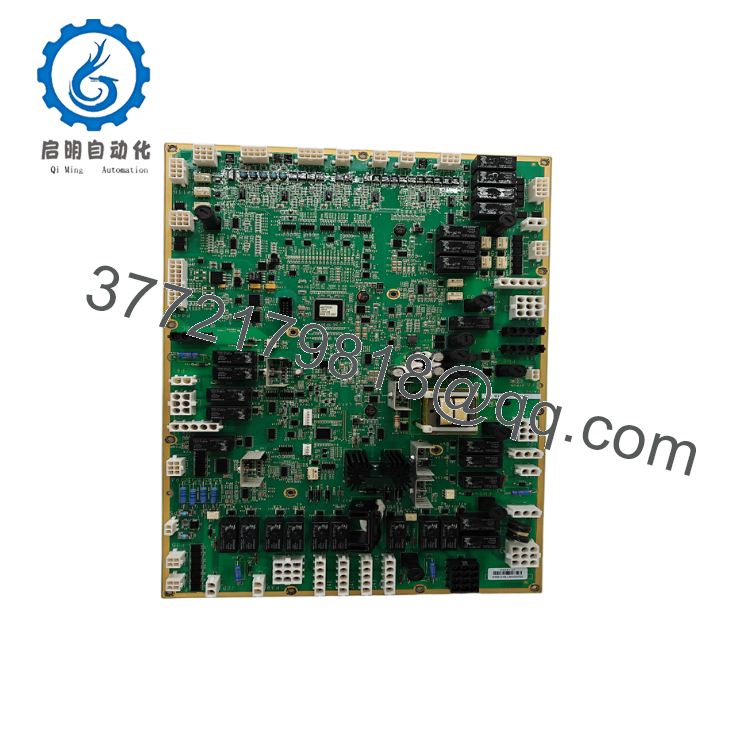
The GE IS200WETBH1B (104W5259P002) is a WETB (Top Box B) printed circuit board designed for the GE Mark VIe Wind control platform. It is installed in the turbine top-box enclosure and serves as an interface between field devices and the central wind turbine controller.
4. Product Introduction
The GE IS200WETBH1B 104W5259P002 is a Top Box B control board used in GE Mark VIe Wind turbine control systems. It manages communication between field-mounted sensors, actuators, and the central turbine controller while supporting distributed I/O functions within the nacelle top-box assembly.
This board is commonly found in GE 1.5 MW wind turbines and related Mark VIe Wind installations. Before replacement, verify the board revision, control software version, wiring configuration, and hardware compatibility with the existing turbine controller.

- IS200WETBH1B 104W5259P002
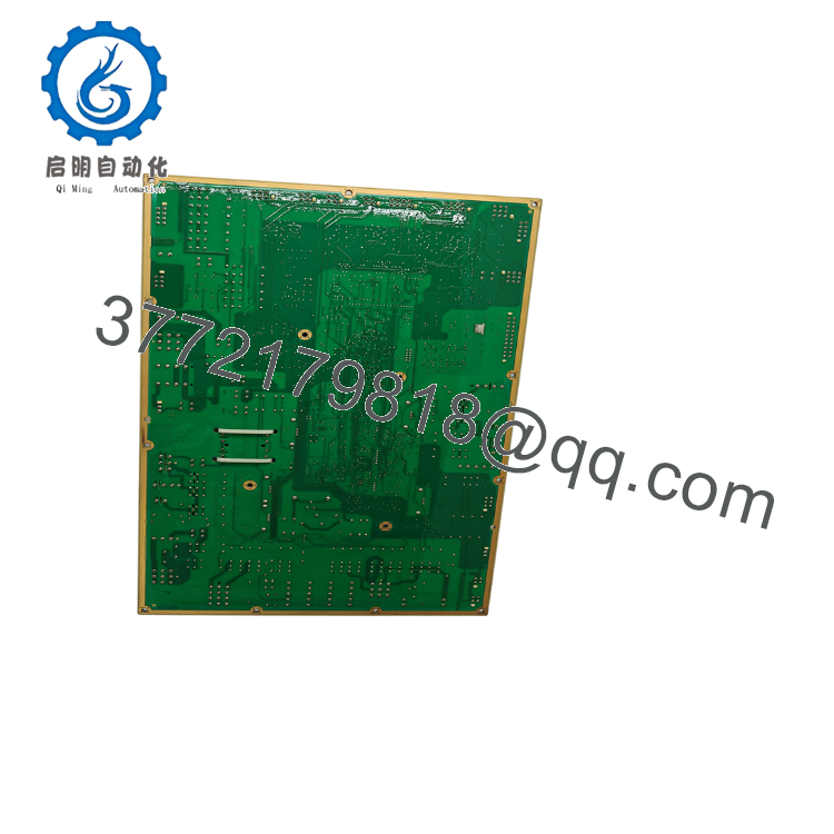
- IS200WETBH1B 104W5259P002
5. Installation & Configuration Guide
Stage 1 – Pre-Installation Preparation (15 Minutes)
⚠️ Safety First
- Notify operations that the turbine will be unavailable.
- Stop the turbine using the approved shutdown sequence.
- Apply Lockout/Tagout (LOTO).
- Isolate cabinet power.
- Wait at least 5 minutes for DC bus capacitors to discharge.
Tools Required
- ESD wrist strap
- PH1 screwdriver
- Fluke 115 digital multimeter
- Wire markers
- Smartphone for wiring documentation
- Laptop with GE ToolboxST
Data Backup
Before removing the board:
- Export the ToolboxST project.
- Record controller firmware version.
- Photograph every connector.
- Record Ethernet and CAN network settings.
- Document board revision and serial number.
Stage 2 – Removing the Existing Board (10 Minutes)
- Open the top-box enclosure.
- Verify all power sources are isolated.
- Label every connector before disconnecting.
- Remove communication and field wiring carefully.
- Release retaining hardware.
- Remove the board evenly without twisting.
Inspect:
- Edge connectors
- PCB guides
- Connector pins
- Signs of moisture or corrosion
⚠️ Do not discard the original board until the replacement has completed operational testing.
Stage 3 – Installing the New Board (15 Minutes)
- Wear a grounded ESD wrist strap.
- Verify:
- Model: IS200WETBH1B
- Part Number: 104W5259P002
- Confirm hardware revision compatibility.
- Reinstall using the original mounting position.
- Reconnect all wiring according to photographs.
- Verify Ethernet, RS-485, and CAN connections where used.
Installation Checklist
- Model verified
- Revision verified
- Connectors fully seated
- Wiring inspected
- Mounting hardware secured
Stage 4 – Power-On & Testing (30 Minutes)
Pre-Power Inspection
- Verify 24 VDC supply.
- Check cabinet grounding.
- Confirm connector seating.
- Inspect communication cables.
Startup Procedure
- Energize the controller cabinet.
- Observe board LEDs.
- Connect using ToolboxST.
- Confirm board identification.
- Verify communication with field devices.
- Test digital and analog I/O.
- Confirm normal turbine diagnostics.
⚠️ Troubleshooting Note
- No communication: Verify Ethernet and CAN addressing.
- Hardware mismatch: Compare board revision with the ToolboxST hardware database.
- Input faults: Inspect field wiring and connector seating before replacing the board again.
SOP Quality Verification
1. Inbound Inspection & Traceability
Every IS200WETBH1B should undergo:
- OEM label verification
- Serial number recording
- Source documentation review
- Anti-counterfeit inspection
- Visual PCB examination
Inspection criteria include:
- No corrosion
- No PCB repair marks
- No connector damage
- No UV discoloration
- Conformal coating intact
2. Live Functional Testing
Testing should be performed using a genuine GE Mark VIe Wind control rack.
Verification includes:
- Power-on self-test
- LED status verification
- Ethernet communication
- CAN Bus communication
- RS-485 communication where applicable
- Analog and digital I/O simulation
- Continuous operation for more than 24 hours
- Thermal monitoring
A formal functional test report should be generated.
Test photographs and videos should be available upon request.
3. Electrical Parameter Testing
Required inspections include:
- 500 V insulation resistance test (>10 MΩ where applicable)
- Ground continuity verification
- Input voltage measurement
- Connector integrity inspection
4. Firmware & Configuration Verification
Record:
- Hardware revision
- Firmware compatibility
- ToolboxST version
- Communication configuration
- Connector layout
Maintain a photographic record of all cable locations.
5. Final QC & Packaging
Final preparation includes:
- QC inspector approval
- Anti-static ESD packaging
- Bubble-wrap protection
- Heavy-duty corrugated carton
- QC Passed label with inspection date
Technical Pitfalls & Survival Guide
❗ Firmware Revision Compatibility
This board may appear identical across revisions, but firmware compatibility is critical.
I have seen technicians replace a WETB board only to spend hours troubleshooting communication faults because the installed hardware revision did not match the controller database.
Always record the existing revision before ordering.
❗ Connector Placement Errors
The top-box enclosure contains multiple similar connectors.
Take photographs before disconnecting anything.
One misplaced connector can generate multiple sensor faults that appear unrelated.
❗ Communication Network Configuration
The WETB board may communicate through Ethernet, CAN Bus, and RS-485 depending on the turbine configuration.
Replacing the hardware without verifying network settings can result in controller communication alarms even though the board itself is functioning correctly.
❗ Power Supply Capacity
Verify the cabinet power supply before installation.
Measure the 24 VDC rail under load and maintain approximately 20% capacity margin to prevent intermittent startup issues.
❗ Electrostatic Discharge (ESD)
The conformal coating protects against moisture, not static electricity.
Always:
- Wear a grounded wrist strap.
- Handle the PCB only by its edges.
- Place the board on an ESD-safe surface.
Keep these checks in mind and you’ll save yourself most of the rework typically encountered during wind turbine control board replacement.
6. Frequently Asked Questions (FAQ)
Q1. What is the GE IS200WETBH1B 104W5259P002 used for?
It is a Top Box B control board used in GE Mark VIe Wind turbine systems. It interfaces sensors, actuators, and field I/O with the central turbine controller.
Q2. Is this board still manufactured?
No. The IS200WETBH1B is considered a legacy GE Wind platform component. Most available inventory consists of New Original (New Surplus) or professionally tested refurbished units.
Q3. Can I hot-swap this board?
No.
GE wind turbine control hardware should be replaced only after isolating cabinet power. Hot-swapping can damage connectors and create communication faults.
Q4. Will replacing the board erase turbine software?
No.
The application software resides within the controller. However, always back up the ToolboxST project and document network settings before replacing hardware.
Q5. Which wind turbines commonly use this board?
The IS200WETBH1B is commonly associated with GE 1.5 MW wind turbines and is also found in certain related GE Wind platforms, depending on the turbine configuration and revision.
Q6. Why is aftermarket pricing lower than OEM pricing?
Many legacy GE Wind components enter the market through surplus inventory, turbine upgrades, or decommissioned projects.
Before purchasing, verify:
- Hardware revision
- Serial number traceability
- Functional test documentation
- Warranty terms
- Overall condition (New Original / New Surplus or Refurbished)
Q7. What documentation should I request before shipment?
For critical wind turbine applications, request:
- Hardware revision photographs
- Serial number verification
- Functional test report
- 24-hour burn-in record
- Communication test results
- ESD packaging confirmation
- QC inspection report
These documents help reduce commissioning risk and simplify replacement planning for legacy GE Mark VIe Wind control systems.



