
 WhatsApp: +86 16626708626
 Email:
  Phone: +86 16626708626
Description
3. Key Technical Specifications
| Parameter | Specification Value |
| Input Voltage Rating | 125 VDC nominal (supplied via Power Distribution Module) |
| Total Output Power | 400 W continuous maximum |
| Backplane DC Voltages | +5 VDC, ±12 VDC, ±15 VDC, ±28 VDC |
| Dedicated Outputs | 5x PSA +28 VDC outputs, 1x Remote +28 VDC output |
| Specialized Output | PS335 (+335 VDC) for TRPG-connected flame detectors |
| Redundancy Support | Dual-source redundant capability enabled with status ID tracking |
| User Interfaces | 3x Status LEDs (Yellow, Red, Green), 1x Locking Toggle Reset Switch |
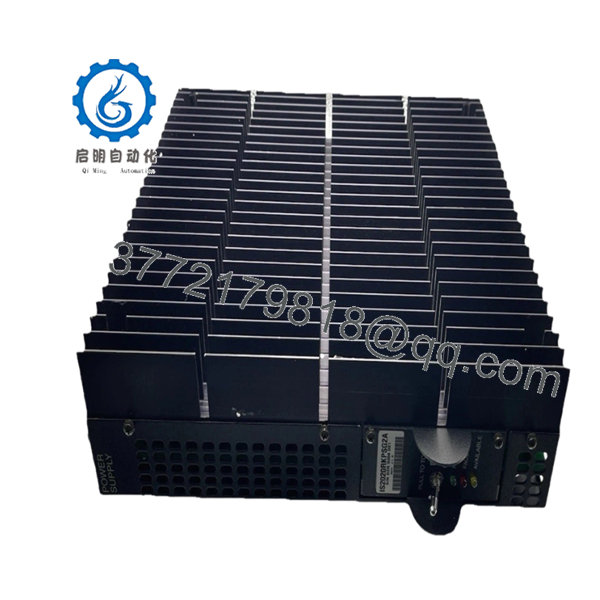
| Cooling Mechanism | Passive convection via integrated heavy-duty metal heat sink fins |
| Circuit Protection | Automatic fold-back current limiting with under-voltage cutoff |
| PCB Conformal Coating | Standard normal coating for industrial environment stabilization |
| Form Factor | Side-mount right-hand VME rack structural bracket module |
4. Product Introduction & Supply Chain Strategy
The GE IS2020RKPSG2A is a high-reliability VME rack power supply module engineered specifically for Speedtronic Mark VI gas and steam turbine control systems. Mounted to the right-hand side of critical VME interface chassis, this 400 W module conditions raw 125 VDC fuel-cell or station battery input into multiple highly regulated DC rails required by core processors and terminal boards. It uniquely integrates a high-voltage 335 VDC circuit essential for driving flame detection arrays, securing real-time ignition and combustion tracking.
From an asset management perspective, securing this component as a New Surplus asset dramatically lowers your Total Cost of Ownership (TCO) compared to the catastrophic financial exposures of secondary-market component failures. Because this series has reached end-of-life status, utilizing reconditioned alternatives introduces hidden reliability liabilities due to capacitor drying and latent semiconductor fatigue under high thermal load. Maintaining a 100% verified New Surplus unit as on-site buffer stock eliminates lead time variability and prevents thousands of dollars per minute in unplanned generation shutdowns.
- IS2020RKPSG2A
5. Installation & Configuration Guide
Stage 1: Pre-Installation (Prep & Safety)
Isolate all upstream power sources supplying the Power Distribution Module (PDM) and execute plant-approved lock-out/tag-out procedures on the 125 VDC feeder circuit. Before unpacking the replacement unit, verify your electrostatic discharge (ESD) workstation setup and attach a grounded wrist strap to an unpainted section of the structural enclosure frame. Use a high-resolution camera to document the target assembly’s physical faceplate switch state, bottom ground cable anchoring paths, and external peripheral jumper configuration.
Stage 2: Removal
Unfasten the locking terminal screws on the bottom DC input line, the PS28 auxiliary connectors, and the specialized PS335 flame detector power cable interface. Disengage the top-mounted PSA and PSB cable harnesses that feed the localized VME backplane segments, taking care not to place tension on the wiring loom. Back out the two front captive retention bolts securing the assembly to the side chassis frame, then carefully slide the bracket assembly outward horizontally along its guide rails to prevent any structural deformation of adjacent VME slots or internal pins.
Stage 3: Installation (Clone & Seat)
Extract the new surplus module from its factory sealed ESD barrier shield and confirm the backplane alignment surfaces show zero transit imperfections. Inspect the configuration jumper block situated on the mounting framework, verifying it perfectly mirrors the prior unit’s operational status (e.g., matching the Normal or Isolated settings for auxiliary peripheral power distribution). Align the housing frame with the right-side VME rack slide paths, glide it smoothly home until the rear alignment pins engage completely, and torque down the four structural mounting fasteners alongside the front captive safety bolts.
Stage 4: Power-On & Testing
Reattach the upper PSA and PSB distribution harnesses, ensuring the connectors click securely into their locked seats. Reconnect the lower input feed lines, applying the specified engineering torque values to prevent localized resistance heating. Apply 125 VDC supply voltage to the rack while monitoring the faceplate diagnostics: the yellow indicator must activate immediately to display valid input line sensing. Pull out and toggle the locking front-panel power switch upward to initialize the module; confirm the green light turns on and the red indicator stays off, signaling stable voltage regulation across all internal rails.
6. Firmware/Software Versions & Upgrade Notes
The IS2020RKPSG2A operates primarily as a hardware-defined analog and switching power regulation unit, meaning it does not carry application-layer control logic. However, its integrated status ID output line relies on localized EEPROM hardware revision coding to report asset tracking data back to the primary Mark VI controller via the VME backplane. This specific functional revision A version features targeted design enhancements that are fully backward compatible with older RKPSG1 infrastructure layout arrays, allowing it to serve as a drop-in physical substitute.
Caution must be exercised during field swaps because mismatching hardware revisions can trigger configuration faults within the Toolset software environment. If replacing a legacy revision module with this updated G2 variant, check that the master diagnostic application is updated to recognize the revised status ID register mapping. Never interrupt input line energy or cycle the physical toggle switch while the primary control processor is performing system configuration uploads, as sudden backplane power dips will corrupt tracking parameters on adjacent communication cards.
7. Frequently Asked Questions (FAQ)
What is the exact physical condition of this IS2020RKPSG2A supply, and how is it verified?
This module is a guaranteed New Surplus unit, sourced directly from verified industrial overstock channels. It has never seen field service, been pulled from an active decommissioned rack, or undergone component-level circuit board repairs. We perform complete inbound inspections, checking backplane contacts for zero tool marking and examining the factory anti-static packaging. Every unit undergoes live test rack verification to prove identical OEM runtime parameters before shipment.
Why is the procurement price higher than refurbished alternatives but lower than direct factory list?
Our pricing structure reflects the substantial capital and verification overhead required to track down, audit, and hold genuine, unused OEM components on a global scale. Refurbished products are typically priced low because they use aged, stressed internal parts with cosmetic touch-ups that present severe operational risks. Buying New Surplus gives you identical OEM reliability and multi-year lifecycle performance without paying the steep premiums and facing the extended factory backorder lead times of current legacy vendor pricing.
What is the practical performance difference between this G2 model and the older G1 version?
The IS2020RKPSG2A is engineered as a direct replacement for the legacy G1 variant, incorporating critical design improvements. The G2 architecture provides enhanced system uptime by incorporating complete redundant operation support and an isolated status ID output line that echoes the faceplate green LED directly back to the central controller rack. To accommodate these diagnostic tracks, the G2 contains two fewer remote outputs, but adds a dedicated PS335 high-voltage circuit to ensure reliable interfacing with specialized industrial flame detectors.
Can this power supply module be hot-swapped while the turbine control system is running?
Absolutely not. Replacing a core VME rack power supply module requires a complete power isolation of that specific control chassis section. Attempting to extract or slide this module out while under load will cause severe electrical arcing across the high-amperage backplane connections, immediately dropping power to all running I/O processors and triggering an emergency turbine trip. Always execute a verified electrical lock-out/tag-out procedure before performing maintenance on this component.
Will replacing this card require reloading or reprogramming the turbine operating software parameters?
No software reload is necessary. The unit does not hold volatile application logic or turbine control code. Its primary duty is providing stable, clean DC power rails to the processors and interface cards that handle the software execution. Once the physical unit is safely mounted, switches configured, and input power is turned back on, the neighboring control cards will boot up normally and pull their necessary operating parameters from the master controller.
What warranty protection is included with this New Surplus inventory asset?
We back this genuine component with a full, comprehensive 1-year operational warranty starting from the date of warehouse receipt. This protective coverage matches traditional factory lifecycles and covers any functional deviations under normal deployment conditions. Because this item has been maintained in climate-controlled, ESD-safe storage conditions, it provides the full expected 10-15 year operational lifespan typical of brand new industrial turbine control components.


