
 WhatsApp: +86 16626708626
 Email:
  Phone: +86 16626708626
Description
3. Key Technical Specifications
| Parameter | Value |
|---|---|
| Manufacturer | GE General Electric |
| Model Number | IS215VPROH2B |
| Product Type | Protection Processor Board |
| Platform | GE Mark VIe |
| Primary Function | Turbine protection and trip logic |
| Redundancy Support | Triple Modular Redundant (TMR) systems |
| Processor Function | Independent protection processing |
| Communication Interface | Mark VIe backplane communication |
| Mounting Method | Rack-mounted PCB module |
| Diagnostic Features | Onboard status and fault LEDs |
| System Application | Gas and steam turbine protection |
| Operating Temperature | 0 °C to 60 °C |
| Storage Temperature | −40 °C to +85 °C |
| Humidity Rating | 5% to 95% non-condensing |
| PCB Revision | H2B |
| Compliance Reference | IEC 61131 industrial control practices |
| Packaging | ESD-safe sealed packaging |
4. Product Introduction
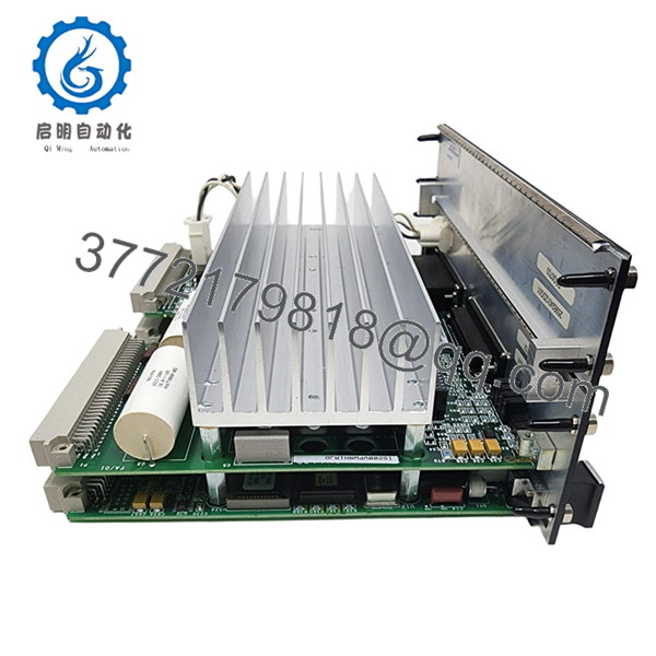
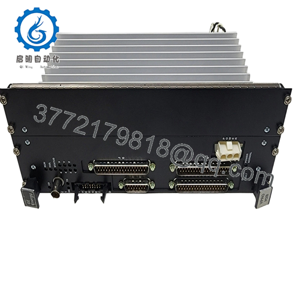
The GE IS215VPROH2B is a Mark VIe protection processor board used in turbine emergency shutdown and protection systems. It performs independent protection logic processing within GE Mark VIe TMR architectures for gas and steam turbine applications.
Plants commonly deploy this board in critical turbine protection cabinets where high availability and deterministic trip response are required. Many facilities continue maintaining these systems because replacing the installed protection architecture usually requires a full turbine controls migration and extended outage planning.
5. Installation & Configuration Guide
Stage 1: Pre-Installation Preparation (Estimated Time: 10–15 Minutes)
⚠️ Safety First
- Coordinate maintenance activity with operations and turbine controls personnel.
- Bring the turbine to a verified safe shutdown condition.
- Apply lock out/tag out procedures to all related control cabinet power sources.
- Wait at least 5 minutes for power supply discharge before opening the cabinet.
Tools Required
- Grounded ESD wrist strap
- PH1 screwdriver
- Fluke 115 multimeter or equivalent
- Wire labels
- Smartphone for configuration photos
- Flashlight for rack inspection
Data Backup
- Export Mark VIe controller and protection configuration files.
- Record the exact rack and slot position.
- Photograph:
- Terminal wiring
- Fiber/copper communication links
- DIP switch settings
- Shield grounding
- Document current firmware revisions from ToolboxST or the engineering workstation.
❗Before you pull anything, capture the firmware version. I’ve seen a replacement board boot fine, then fail TMR synchronization because the firmware jumped one revision beyond the existing protection processors.
Stage 2: Removing the Old Module (Estimated Time: 5–10 Minutes)
- Remove cabinet barriers or front covers carefully.
- Label all associated wiring and communication cables.
- Disconnect connectors without twisting the PCB.
- Release locking tabs or retaining screws.
- Pull the board straight out evenly.
Inspection Checklist
- Inspect backplane connectors for bent pins
- Check for overheating or discoloration
- Remove dust accumulation carefully
- Verify no loose hardware remains inside the rack
⚠️ Note
Keep the original module available during commissioning. It is often the fastest reference source for jumper settings and revision confirmation.
Stage 3: Installing the New Module (Estimated Time: 10–15 Minutes)
- Wear the ESD strap before opening the anti-static packaging.
- Verify the exact model number: IS215VPROH2B.
- Compare hardware revision labels before installation.
Configuration Clone (Crucial)
- Duplicate all jumper and switch settings exactly.
- Verify node addressing and communication settings.
- Confirm grounding and shielding arrangements match the original installation.
❗This is one of the most common field failures. A technician leaves one termination jumper in the default position and suddenly the protection network starts throwing intermittent diagnostics alarms.
Installation Procedure
- Align the board carefully with rack guides.
- Insert evenly until fully seated.
- Tighten retaining hardware securely.
- Reconnect all communication and field connectors.
Self-Checklist
- Hardware revision verified
- Firmware compatibility checked
- Jumpers cloned correctly
- Wiring secured
- Board seated fully
Stage 4: Power-On & Testing (Estimated Time: 20 Minutes)
Pre-Power Check
- Use a multimeter to verify no short exists on the 24 V rail.
- Confirm proper grounding continuity.
- Inspect communication cable seating.
Power-On Procedure
- Energize the Mark VIe rack first.
- Observe startup indicators:
- Green RUN = Normal operation
- Red FAIL/ERR = Fault detected
- Connect ToolboxST or the approved engineering software.
- Verify:
- Processor recognition
- TMR synchronization
- Firmware version
- Diagnostic health
- Restore configuration files if required.
- Conduct dry-run permissive and trip validation tests before returning the turbine to service.
⚠️ Troubleshooting Notes
- Solid red fault LED: Usually firmware mismatch or failed synchronization.
- TMR disagreement alarms: Check revision consistency across all protection processors.
- No communication: Verify backplane seating and Ethernet/fiber connections.
I’ve seen engineers chase phantom turbine trip logic for hours when the real issue was one processor running a different firmware build than the other two TMR legs.
Technical Pitfalls & Survival Guide
❗ Firmware Revision Mismatch
This is the biggest trap with Mark VIe protection hardware.
Before replacement:
- Record all processor firmware versions
- Verify approved firmware matrix
- Confirm ToolboxST project compatibility
One refinery startup lost nearly a full shift because one replacement board shipped with newer firmware that altered synchronization timing slightly.
❗ DIP Switch / Jumper Errors
Default factory settings rarely match the running system.
Before removing the old board:
- Photograph every switch position
- Zoom in clearly
- Verify node addressing manually
Do not trust memory during outage pressure.
❗ Terminal & Connector Variations
Even similar GE revisions can differ internally.
Always verify:
- Connector orientation
- Shield grounding
- Pin assignments
- Fiber/copper network mapping
Never wire based only on cabinet labels.
❗ Power Supply Headroom
Protection racks run hot, especially in older cabinets.
Before startup:
- Check rack PSU loading
- Verify fan operation
- Leave at least 20% power margin
An overloaded power supply can create intermittent TMR faults that look like processor failures.
❗ Electrostatic Discharge (ESD)
These boards are extremely sensitive to static damage.
Use:
- Grounded wrist strap
- ESD-safe work surface
- Anti-static packaging
I watched a contractor unpack one of these boards on a dry winter morning without grounding himself. The module failed diagnostics immediately after boot.
Keep these checks in mind and you’ll save yourself 90% of typical rework time.

- IS215VPROH2B
- IS215VPROH2B
6. Frequently Asked Questions (FAQ)
Q1: Can I hot-swap the GE IS215VPROH2B?
No. This board is part of the turbine protection system. Removing it under power can trigger protection faults, synchronization failures, or unintended trips. Always isolate cabinet power before replacement.
Q2: Is the IS215VPROH2B obsolete?
Yes. The Mark VIe family remains widely installed, but many hardware revisions are now classified as legacy support items. Availability depends largely on surplus OEM inventory and specialized industrial stock.
Q3: Is this module genuinely new?
This inventory is classified as New Original / New Surplus unless otherwise stated.
Typical verification includes:
- Serial number inspection
- PCB visual inspection
- Communication diagnostics
- Functional power-on testing
- ESD-safe packaging
Inspection photos and test records are available upon request.
Q4: Will replacing this board erase my turbine logic?
Normally, no. Primary application logic and configuration are maintained within the Mark VIe control environment. However, always perform a full backup before maintenance work.
I’ve seen engineers assume redundancy would protect them automatically, only to discover mismatched configuration files after startup.
Q5: What is the biggest compatibility risk with this module?
Firmware mismatch inside the TMR architecture.
If one processor runs a different firmware revision:
- Synchronization can fail
- Diagnostic alarms appear
- Protection voting behavior may become unstable
Always verify all three protection processors use approved compatible revisions.
Q6: Why are prices inconsistent between suppliers?
Traceability and testing standards vary significantly in the surplus controls market.
Lower-priced boards may:
- Lack test documentation
- Have uncertain storage history
- Be repaired instead of original
- Skip load testing entirely
Ask for:
- Serial photos
- Test reports
- Firmware verification
- Packaging documentation
Q7: What testing is typically performed before shipment?
Standard QC procedures generally include:
- Inbound Inspection & Traceability
- OEM label verification
- Serial number checks
- Visual PCB inspection
- Connector integrity audit
- Functional Testing
- Installed into a genuine Mark VIe test rack
- Power-on diagnostics
- Communication handshake verification
- Continuous runtime observation
- Electrical Testing
- Ground continuity check
- Insulation resistance verification
- Basic voltage rail validation
- Final QC & Packaging
- QC sign-off
- ESD sealing
- Reinforced export packaging
- QC date labeling
Test videos and inspection photos are available upon request.


