
 WhatsApp: +86 16626708626
 Email:
  Phone: +86 16626708626
Description
Key Technical Specifications
- Model: MIVII1000E00HI00
- Canonical Catalog Format: MIVII-1000E00HI00
- Manufacturer: GE Multilin / GE Grid Solutions
- Product Family: Multilin MIV II
- Protection Class: Three-phase and ground voltage protection relay
- Voltage Function: MIV II 1000 voltage model
- Voltage Input Range: 10 to 250 V
- Power Supply Type: HI high-range supply
- DC Power Supply: 110 to 250 VDC nominal; 88 to 300 VDC operating range
- AC Power Supply: 110 to 230 VAC nominal; 88 to 264 VAC operating range
- AC Frequency: 48 to 62 Hz
- Maximum Power Consumption: 15 W
- Front Communications: RS-232, DB9 connector
- Rear Communications: RS-485
- Communications Protocol: Modbus RTU
- Communications Speed: 300 to 19,200 bps
- Digital Inputs: Two fixed inputs; optional configurable assignments vary by hardware
- Digital Outputs: Six fixed outputs; optional configurable outputs vary by hardware
- Event Recording: 24-event record
- User Interface: Front keypad and display
- Operating Temperature: 0 to 55 °C; verify the relay nameplate and manual revision
- Storage Temperature: −40 to 85 °C
- Relay Addressing: Front-panel configurable for serial communications
- Network Capacity: Up to 32 GE Multilin devices on one RS-485 communication circuit
Product Introduction
The GE Multilin MIVII1000E00HI00, also designated MIVII-1000E00HI00, is a high-range MIV II numerical relay for three-phase and ground voltage protection. It accepts 10 to 250 V voltage inputs and provides front RS-232 and rear RS-485 communications using Modbus RTU.
The HI power-supply option accepts 110 to 250 VDC or 110 to 230 VAC. The relay provides configurable voltage protection, frequency-related functions associated with the MIV II platform, event recording, digital inputs, relay outputs, and front-panel settings. Confirm the complete suffix and protection scheme before replacing an installed relay.
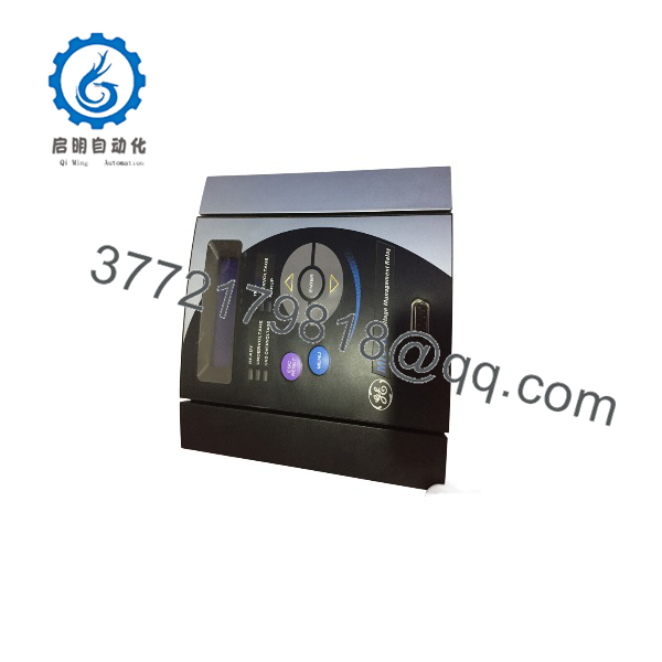
MIVII1000E00HI00
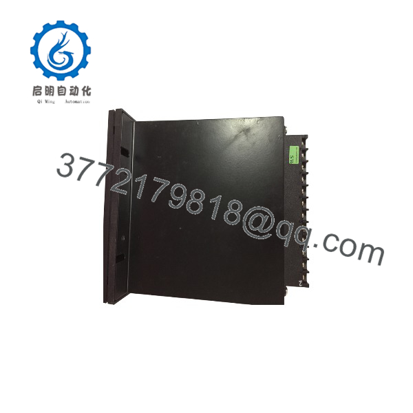
MIVII1000E00HI00
Installation & Configuration Guide
Stage 1: Pre-Installation Preparation — 10 to 15 Minutes
⚠️ Safety First: Notify operations, obtain the approved switching and protection-work permit, and place the protected circuit in a safe state. Isolate CT/PT sources and control power according to the site procedure. Never open-circuit an energized current-transformer secondary.
Tools Required:
- ESD wrist strap and grounded ESD mat
- PH1 screwdriver and suitable terminal tools
- CAT-rated multimeter
- Wire labels and marker
- Smartphone or camera for photographs
- Laptop with GE EnerVista MII Setup or the approved MIV II configuration software
- Approved test set for voltage-relay secondary injection
Data Backup:
- Download and save the existing relay settings before removing power.
- Record the complete catalog number, serial number, firmware version, and hardware revision.
- Export or photograph all voltage, frequency, delay, pickup, output, and digital-input settings.
- Record the Modbus RTU address, baud rate, parity, stop bits, and RS-485 wiring polarity.
- Photograph the rear terminal wiring, front RS-232 connection, rear RS-485 connection, and relay mounting position.
- Confirm that the replacement uses the HI power-supply range. Do not connect a 110–250 V supply to an LO-rated relay.
Stage 2: Removing the Old Relay — 5 to 10 Minutes
- Open the protection panel under the approved electrical safety procedure.
- Verify that relay control power is isolated.
- Confirm that CT and PT circuits are safely isolated or bypassed as required by the protection scheme.
- Label every voltage input, digital input, output contact, communication conductor, and power terminal.
- Disconnect the front RS-232 cable and rear RS-485 cable without pulling on the connector body.
- Remove the relay mounting hardware and withdraw the unit without stressing the terminal blocks.
- Inspect the panel cutout, terminal wiring, grounding, communication cable, and surge-protection components.
- Keep the old relay available until the replacement has completed settings verification and secondary-injection testing.
Stage 3: Installing the New Relay — 10 to 15 Minutes
- Put on the grounded ESD wrist strap and verify the replacement label reads MIVII1000E00HI00 or MIVII-1000E00HI00.
- Confirm the HI power-supply rating before connecting any control power.
- Install the relay in the original panel position and secure the mounting hardware evenly.
- Reconnect voltage inputs using the original phase identification and polarity.
- Reconnect digital inputs and output contacts according to the saved wiring diagram.
- Reconnect the RS-485 conductors with correct polarity, shield treatment, and termination arrangement.
- Reconnect the front RS-232 cable only after confirming the laptop interface is correctly isolated.
- Verify that output contacts are wired to the intended trip, alarm, and control circuits.
- Do not energize the relay until the power-supply range, PT voltage, terminal wiring, and CT/PT isolation are independently checked.
Self-Checklist:
- Complete model and HI suffix verified
- [] Control-power range confirmed
- [] PT voltage and phase sequence checked
- [] CT/PT safety procedure completed
- [] Digital inputs and outputs matched
- [] RS-485 polarity verified
- [] Modbus address documented
- [] Relay securely mounted
- [] Trip and alarm wiring independently checked
Stage 4: Power-On and Testing — 15 to 30 Minutes
- Measure the incoming control power before connecting it to the relay.
- Energize the relay with the protected breaker or switching device held in the approved safe state.
- Confirm the display, keypad, status indicators, and self-diagnostics complete startup.
- Verify the relay model, firmware, nominal frequency, voltage scaling, and power-supply configuration.
- Load the backed-up settings only after confirming the replacement hardware is compatible.
- Set the Modbus RTU address, baud rate, parity, and stop bits to match the substation or plant SCADA configuration.
- Confirm RS-232 communication locally, then verify RS-485 communication from the host system.
- Perform secondary voltage injection for the applicable phase, ground, undervoltage, overvoltage, and frequency elements.
- Verify pickup values, time delays, trip outputs, alarm outputs, digital-input blocking, and event records.
- Confirm the relay returns to the correct normal state and that SCADA receives the correct status and measured values.
- Remove test sources, restore the protection circuit, and return the breaker or switching device to service under the approved procedure.
⚠️ Troubleshooting Note: If the relay does not power up, check the HI supply range, control-power polarity, fuse, and terminal connections. If Modbus communication fails, verify the relay address, RS-485 polarity, termination, baud rate, parity, and whether another device has the same address. If protection pickup is incorrect, check PT scaling, phase sequence, voltage-input wiring, and the loaded settings file.
Frequently Asked Questions (FAQ)
What is the GE MIVII1000E00HI00?
It is a GE Multilin MIV II voltage protection relay, also written as MIVII-1000E00HI00. The 1000 model provides voltage-protection functions over a 10 to 250 V input range, while the HI suffix identifies the high-range auxiliary power supply.
What does the HI suffix mean?
HI identifies the high-range control-power option: 110 to 250 VDC or 110 to 230 VAC nominal. The relay accepts wider operating ranges, but the actual supply must remain within the documented limits. Applying a low-range 24/48 VDC supply or an incorrectly wired high-voltage source can prevent operation or damage the relay.
Does this relay support Modbus RTU?
Yes. The MIV II provides a front RS-232 port and rear RS-485 port using Modbus RTU. Baud rates range from 300 to 19,200 bps, and up to 32 GE Multilin devices can share one RS-485 communication circuit when addressing and termination are correctly configured.
Is MIVII1000E00HI00 a direct replacement for every MIV II relay?
No. Match the complete catalog number, voltage-input range, power-supply suffix, frequency option, terminal arrangement, firmware, and protection settings. An LO-powered relay, a 2 to 60 V model, or a different MIV II function set is not automatically interchangeable with this HI 10 to 250 V model.
Will the protection settings remain after replacing the relay?
Do not rely on the replacement retaining the installed settings. Download the original settings and event information before removal, then verify every pickup, delay, input, output, communication, and frequency parameter after loading the file. Complete secondary-injection testing; a successful settings download does not prove correct PT scaling or trip logic.
Can I connect this relay directly to a PLC or SCADA system?
Yes, if the host supports Modbus RTU and the communication wiring is correctly engineered. The relay does not provide native EtherNet/IP or standard Ethernet communication through the listed MIV II serial ports. Use an approved RS-485 interface or protocol gateway when the SCADA or PLC network requires another protocol.
Is this model obsolete, and is it genuinely new?
The MIV II is a legacy GE Multilin relay family, so stock may be factory-sealed, new surplus, used, or refurbished. Require a clear condition statement, relay nameplate photograph, serial-number traceability, firmware information, and warranty terms. A supplier’s claim of “tested” should include power-on diagnostics, communication testing, output-contact checks, and protection-function testing.
What testing should the supplier provide?
Request a documented inspection, HI power-input test, front RS-232 and rear RS-485 communication test, display and keypad verification, digital-input and output-contact test, and secondary voltage-injection report. The test report should identify the firmware, settings file, relay serial number, test equipment, and measured pickup and operating times. Test photographs and videos should be available upon request; verify the protection application against the OEM manual before energizing the relay.



