WhatsApp: +86 16626708626
 Email:
 Phone: +86 16626708626
Description
Core Product Summary (Brand / Model / Key Attributes)
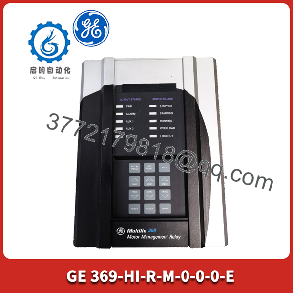
The GE Multilin 369-HI-R-M-0-0-0-E is a digital motor management relay designed to protect, monitor, and control medium-voltage three-phase induction motors and associated driven equipment. As a core member of the GE Multilin 369 series, this comprehensive protection device incorporates high-power control power supply architecture, internal output relay trip logic, enhanced memory profiling, and physical continuous-monitoring hardware capabilities within a compact panel-mount enclosure.
Engineered to prevent motor thermal damage, stator failure, mechanical overload, and electrical fault conditions, the relay processes current, voltage, and RTD temperature inputs to calculate precise thermal capacity models in real time. The unit features built-in Modbus communications for SCADA network integration, programmable control output contacts, and front-panel LED status displays, making it a critical protection component across power plants, chemical processing facilities, mining operations, and heavy industrial water processing plants.
Key Technical Specifications
| Specification | Verified Parameter |
| Manufacturer / Brand | GE Multilin (General Electric) |
| Product Family | 369 Motor Management Relay Series |
| Exact Order Code | 369-HI-R-M-0-0-0-E |
| Control Power Supply (HI) | High-Power Range: 90–300 VDC / 70–265 VAC |
| Output Relays (R) | Standard Output Relays (Trip, Alarm, Auxiliary) |
| Memory Profile (M) | Enhanced Memory with Data Logger & Event Recording |
| Harsh Environment Coating (E) | Harsh Environment Conformal Coating Option |
| Display & User Interface | Integrated Front Panel Display with Navigation Keypad |
| Communication Protocols | RS485 Modbus RTU / Serial Communications |
Detailed Product Overview
The GE Multilin 369-HI-R-M-0-0-0-E serves as an intelligent protection and diagnostic hub for critical medium-voltage electric motors. By replacing separate thermal overload relays, phase-loss monitors, and mechanical timing devices, it unifies motor protection, operational monitoring, and fault record metering into a single micro-controller-based device.
Within complex industrial automation networks, the relay evaluates real-time current transformer (CT) input signals and temperature measurement sensors to construct a dynamic thermal model of the connected motor. This allows the system to permit safe motor restarts while preventing insulation breakdown caused by excessive thermal stress, frequent starting cycles, or locked-rotor conditions. The specific “E” configuration prefix designates enhanced conformal coating on internal electronic circuit boards, providing protection against corrosive atmospheric contaminants, airborne dust, and high moisture levels commonly encountered in harsh industrial environments.
369-HI-R-M-0-0-0-E
Engineering Selection Highlights
- Specific Order Code Decoding: Configured with High Control Power Supply (90–300 VDC / 70–265 VAC), standard output relays, expanded memory profile, and enhanced conformal coating.
- Dynamic Thermal Modeling: Continually updates the calculated thermal capacity used (% TCU) to protect motor stator and rotor windings from over-temperature failure.
- Harsh Environment Protection: Features conformal-coated internal electronics designed to resist corrosion and degradation in hostile industrial atmospheres.
- Expanded Event Logging: Incorporates the expanded memory option to store historical trend data, trip records, wave-shape event files, and motor start profiles.
System Compatibility & Integration Requirements
| Item / Dependency | Verified Compatibility or Requirement | Practical Note |
| Control Power Supply | 90–300 VDC or 70–265 VAC Power Source | Verify auxiliary supply voltage limits prior to applying station control power. |
| Current Transformers (CTs) | 1A or 5A Secondary Phase & Ground CTs | Match internal CT ratio software settings to external physical instrument transformer specifications. |
| Software & Setup | EnerVista 369 Setup Software | Connect via front RS232 port or rear RS485 network to configure protection curves and setpoints. |
Dimensions, Mounting & Connection Notes
- Enclosure & Mounting: Standard drawout or compact panel cutout mounting design; secure firmly into switchgear or control cabinet doors using the provided mounting hardware.
- Terminal Connections: Heavy-duty screw terminals located on the rear chassis for CT inputs, control power, output relay contacts, and RS485 communication lines.
- Wiring Isolation: Route low-voltage signal cables (RTDs and communication lines) in separate conduits away from high-voltage current transformer secondaries and power switching circuits.
FAQ
What is the GE Multilin 369-HI-R-M-0-0-0-E?
It is a digital motor management relay designed to provide comprehensive protection, monitoring, and control for industrial medium-voltage induction motors.
What does the “HI” specification indicate in the order code?
The “HI” code indicates a high-range control power supply designed to accept 90–300 VDC or 70–265 VAC auxiliary power input.
What does the “E” suffix represent?
The “E” suffix specifies the harsh environment option, meaning the internal circuit boards feature a protective conformal coating to guard against corrosive environments.
How does the relay communicate with plant SCADA systems?
It communicates via built-in serial ports using standard Modbus RTU protocols to stream metering data, alarm statuses, and operational parameters.
Which software tool is used to program the unit?
The unit is configured using GE’s EnerVista software suite via a direct serial connection or network port.
Verification & Troubleshooting Notes
- Control Power Inspection: If the front display remains dark, measure the auxiliary input voltage across the power supply terminals to ensure it falls within the required 90–300 VDC or 70–265 VAC operational range.
- Thermal Capacity Lockout: If the relay prevents a motor start due to a thermal trip, verify the calculated Thermal Capacity Used (% TCU) on the display; wait for motor cooling or check if CT programming ratios match actual hardware ratings.
- RS485 Communication Errors: Verify correct RS485 bus termination, polarity matching (+/-), unique Modbus slave addressing, and matching baud rate settings between the relay and the master network node.