
 WhatsApp: +86 16626708626
 Email:
  Phone: +86 16626708626
Description
Key Technical Specifications
- Application: GE Multilin SR469 Motor Management Relay
- Construction: Fixed companion case for a removable drawout relay unit
- CT Safety Feature: Automatic CT shorting during relay withdrawal
- Mounting: Panel mount or 19-inch rack installation
- Maximum Case Depth: 8.80 in (224 mm)
- Panel Cutout Height: 7.52 in (191 mm)
- Panel Cutout Width: 8.52 in (216 mm)
- Relay Overall Height: 9.93 in (252 mm)
- Relay Overall Width: 9.00 in (229 mm)
- Reduced Cutout Dimension: 7.25 in (184 mm), configuration-dependent
- Field Wiring: Permanent termination through the fixed case
- Compatible Relay: GE Multilin SR469; verify relay revision and option code before installation
- Manufacturing Status: Discontinued by GE Vernova; GE identifies the Multilin 469 as a legacy product and points users toward the 859 or 869 as alternatives.
Product Introduction
The GE Multilin SR469-CASE is the fixed panel case for the SR469 motor management relay. It houses the removable relay chassis, provides termination for external CT, VT, control, I/O, and communications wiring, and automatically shorts CT circuits when the relay is withdrawn.
This is not a complete SR469 relay. The case is selected when the existing enclosure, terminal wiring, or CT connections remain serviceable but the case is damaged or missing. Confirm the relay option code, terminal arrangement, mounting dimensions, and case condition before ordering.
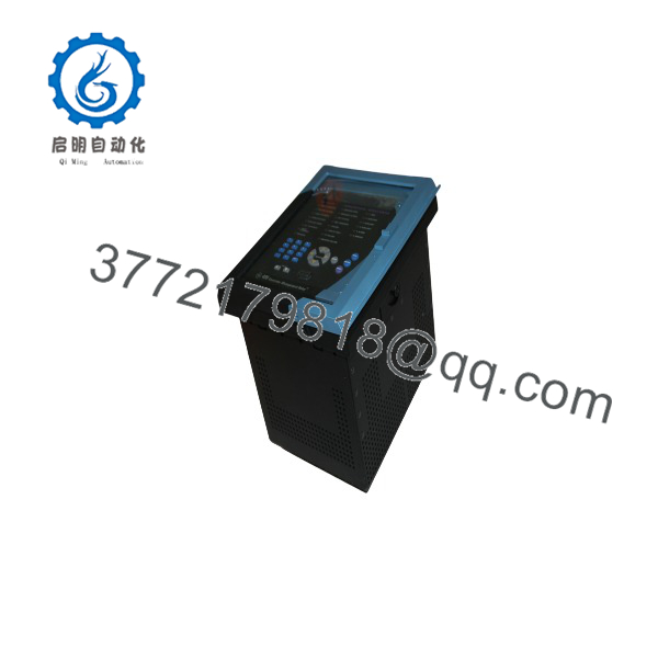
SR469-CASE
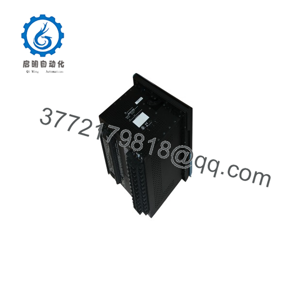
SR469-CASE
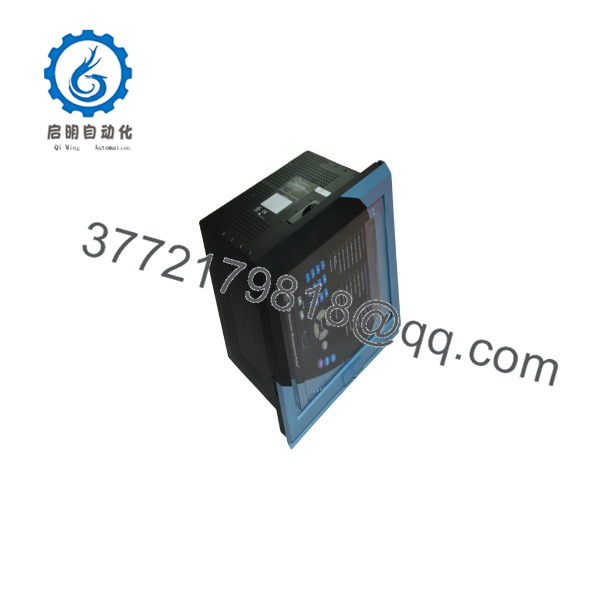
SR469-CASE
Troubleshooting Quick Reference
| Symptom | Possible Cause | Relevance to This Part | Quick Check Method | Recommendation |
|---|---|---|---|---|
| SR469 relay has no display or LEDs | Missing control power, blown fuse, or failed relay chassis | ❌ Low | Measure the correct control voltage at the relay terminals; the case itself does not generate control power | Check the power source, external fuse, and drawout relay before replacing the case |
| CT circuit remains open during relay withdrawal | Damaged or contaminated automatic CT-shorting mechanism | ✅ High | With power isolated and CT safety procedures followed, inspect the case shorting contacts and verify continuity according to the manual | Do not energize the motor circuit until CT shorting has been verified |
| Current readings are zero or incorrect | Open CT wiring, wrong CT secondary option, or poor terminal contact | ✅ Medium | Verify phase CT wiring, terminal tightness, CT secondary setting, and continuity through the case terminals | Confirm the case terminal arrangement matches the installed option |
| Voltage readings are incorrect | VT wiring error, loose terminal, or incorrect VT ratio setting | ✅ Medium | Compare field wiring with the schematic; measure VT input voltage only with appropriately rated test equipment | Correct wiring or relay settings before replacing the case |
| RS485 communication fails after case replacement | Reversed polarity, missing shield termination, or loose communication terminal | ✅ Medium | Check RS485 polarity, termination, shield grounding, slave address, baud rate, and Modbus RTU parity | Reproduce the original wiring exactly; do not assume similar terminal positions are identical |
| Relay cannot be fully inserted | Bent connector, damaged guide hardware, or incompatible case | ✅ High | Inspect the drawout guides, rear connectors, alignment hardware, and relay model code without forcing insertion | Stop if mechanical resistance occurs; forced insertion can damage the relay and case |
| Output relays operate incorrectly | Wrong field wiring or damaged terminal connection | ✅ Medium | Perform point-to-point continuity checks with control power isolated; compare each circuit against the approved wiring diagram | Verify the case terminal block and wiring before condemning the relay |
| Case shows corrosion, cracked insulation, or heat damage | Environmental exposure or previous electrical fault | ✅ High | Inspect terminal hardware, CT shorting contacts, insulation, labels, and rear connectors under good lighting | Reject the case or request inspection photographs and a test report |
| Relay reports internal diagnostics or communication errors | Failed chassis, firmware mismatch, or configuration problem | ❌ Low | Record the diagnostic message, firmware revision, setpoints, and communication parameters using the front panel or 469PC software | Test the relay in a known-good case before purchasing another case |
| Replacement case does not match the panel opening | Different mounting arrangement or accessory collar configuration | ✅ High | Measure the existing cutout and compare it with the case drawing; check whether a 1-inch or 3-inch collar is installed | Confirm mechanical dimensions and accessories before shipment |
Important: The -CASE is a passive mechanical and termination assembly. Many “case” problems actually originate in the relay chassis, control power, CT/VT wiring, or configuration. Contact technical support with clear photos of the case, terminal areas, nameplate, relay option code, and diagnostic logs if the fault remains unresolved.
Frequently Asked Questions (FAQ)
Is -CASE a complete motor protection relay?
No. -CASE is the fixed companion case for the GE Multilin drawout relay. The removable relay chassis, display, processor, protection functions, communications electronics, and settings are separate. Verify that the listing includes the relay chassis if you need a complete operating unit.
Can I use this case with any relay?
Use it only after confirming the relay model, terminal layout, control-power option, CT configuration, and mounting arrangement. GE order codes include options such as 1 A or 5 A phase CT inputs, low- or high-range control power, and 0–1 mA or 4–20 mA analog outputs. Similar-looking cases should not be assumed interchangeable.
Can I hot-swap the relay in this case?
The uses a drawout construction, but that does not mean every withdrawal or insertion operation is safe under energized conditions. Follow the GE installation procedure, isolate circuits as required, and verify the automatic CT-shorting mechanism before removing the relay. Never open-circuit an energized CT secondary.
Will my programming remain intact when I replace the case?
The settings are stored in the relay chassis, not in the passive case. Replacing the case normally does not erase relay programming. Still, record the setpoints, firmware revision, CT ratios, VT ratio, communication parameters, and wiring before removal. This protects against configuration loss if the relay also requires replacement.
Is the GE Multilin -CASE obsolete?
Yes. GE Vernova lists manufacturing for the Multilin 469 as discontinued and identifies the 859 and 869 relays as current alternatives. Existing plants may still require an -CASE to preserve installed wiring and panel dimensions, so availability depends on surplus and used inventory.
Why is this case cheaper than a factory-complete relay?
The case is a passive enclosure and termination assembly. It does not include the processor, display, protection firmware, communications hardware, or complete relay chassis. Price also depends on whether the unit is New Original, New Surplus, or Refurbished. Request photos of the terminal side, CT shorting mechanism, labels, and mounting hardware before purchasing.
What should I verify before ordering?
Confirm the exact part marking, case dimensions, terminal condition, drawout hardware, CT-short functionality, and compatibility with your relay option code. Also confirm condition, warranty period, stock status, and lead time in writing. The manufacturer documentation provides the mechanical and electrical installation details; verify the precise compatibility against the OEM manual before energizing the system.



