WhatsApp: +86 16626708626
 Email:
 Phone: +86 16626708626
Description
Core Product Summary (Brand / Model / Key Attributes)
The GE Multilin UR-8FH is a standard Current Transformer / Voltage Transformer (CT/VT) input module designed for installation within GE Multilin Universal Relay (UR) family chassis. Functioning as an analog processing interface, it scales high-voltage and high-current power system signals down to low-level secondary values required by the relay’s central processing unit for protection, control, metering, and fault recording applications.
Model code configuration UR-8FH specifies a standard 4CT/4VT input channel configuration. It includes three 1A/5A phase current transformer inputs, one 1A/5A ground current transformer input, and four voltage transformer inputs. Housed in a slide-in form factor designed for UR series backplanes, the module provides isolated analog sampling across 8 dedicated channels, split into two 4-channel groups for system protection architectures.
Key Technical Specifications
| Parameter | Specification |
| Model Number | UR-8FH (UR8FH) |
| Product Family | GE Multilin Universal Relay (UR) Series |
| Module Type | Standard CT/VT Analog Input Expansion Module |
| Total Channels | 8 Channels (4 CT / 4 VT) |
| Phase CT Inputs | 3 × 1A / 5A selectable phase CT inputs |
| Ground CT Inputs | 1 × 1A / 5A ground CT input |
| VT Inputs | 4 × Voltage Transformer (VT) inputs |
| Channel Grouping | 2 groups (Channels 1–4 and Channels 5–8) |
| Secondary Current Rating | Dual 1 A / 5 A secondary nominal field CT inputs |
| Chassis Interface | UR Series backplane slot connection |
Detailed Product Overview
The GE Multilin UR-8FH CT/VT module serves as an analog input acquisition card for the GE Universal Relay platform. In electrical substation and industrial power automation systems, protective relays require accurate step-down conversion of primary system currents and voltages. The UR-8FH bridges primary instrumentation transformers and the digital signal processing architecture of the UR chassis.
The module provides eight physical analog measurement channels arranged into two balanced 4-channel blocks. Channels 1 through 4 handle three-phase current monitoring (Phases A, B, C) alongside a dedicated ground current input. Channels 5 through 8 process voltage signals, allowing the host relay to calculate active power, reactive power, power factor, frequency, phase angles, and impedance parameters. Dual 1A and 5A secondary current ratings allow compatibility with standard current transformer secondaries without requiring separate hardware ordering variants.
Because the UR-8FH is a standard 4CT/4VT configuration without a sensitive ground CT channel, it is intended for standard phase and high-impedance grounded system applications. The module slides directly into designated CT/VT slots of a 19-inch UR full-slot or half-slot chassis, establishing power and internal data connections through the backplane while exposing field wiring terminal blocks on the rear panel.
Engineering Selection Highlights
- Standard 4CT/4VT Configuration → Combines 3 phase CTs, 1 ground CT, and 4 VTs into a single slot module, eliminating the need for separate standalone voltage and current sensing cards.
- Dual 1A / 5A Secondary CT Rating → Provides software/hardware selectable 1A and 5A secondary current capability to simplify inventory and adapt to varying substation CT ratios.
- 8-Channel Analog Acquisition → Delivers high-speed analog sampling across two 4-channel groups to feed relay protection algorithms, harmonic monitoring, and fault record capture.
- Native UR Chassis Compatibility → Integrates directly into standard GE Multilin Universal Relay backplane slots for modular assembly, upgrade, or replacement.
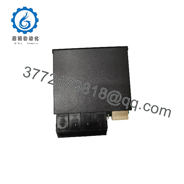
UR-8FH
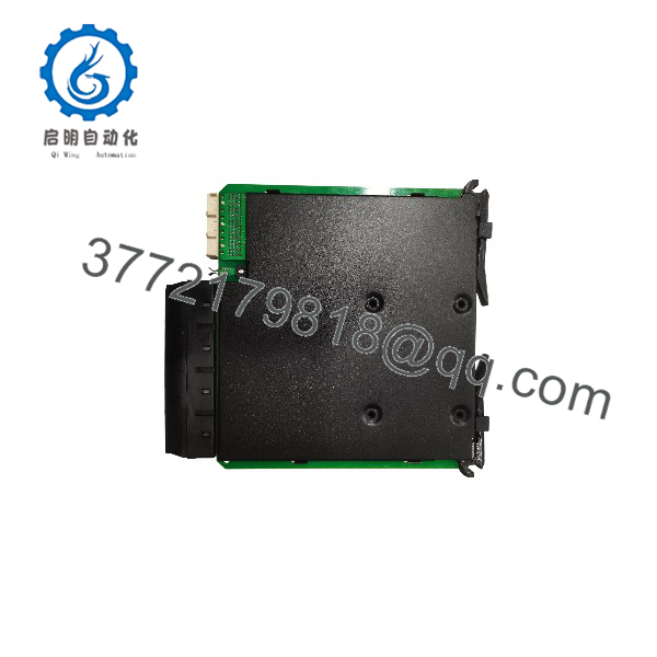
UR-8FH
System Compatibility & Integration Requirements
| Item / Dependency | Verified Compatibility or Requirement | Practical Note |
| Host Platform | GE Multilin Universal Relay (UR) Series | Fits designated CT/VT module expansion slots within UR chassis assemblies. |
| Primary CT Interface | 1A or 5A secondary rated Current Transformers | Field wiring connects to rear terminal block positions dedicated to 1A/5A CT taps. |
| Primary VT Interface | Standard secondary Voltage Transformers | Accepts standard line-to-neutral or line-to-line secondary VT wiring. |
| Grounding Application | Standard phase / High-impedance ground systems | Lacks sensitive ground CT hardware; for zero-sequence/sensitive ground sensing, specific sensitive ground CT modules (e.g., UR-8G, UR-8J) are required. |
Dimensions, Mounting & Connection Notes
- Form Factor: Modular expansion card designed for insertion into GE Universal Relay chassis slots.
- Dimensions: Approximately 15 cm (H) × 18 cm (D) × 4 cm (W).
- Mounting: Slide-in backplane alignment with rear panel retaining screws to secure the card within the relay chassis.
- Field Connections: Heavy-duty terminal block interface on the rear assembly for CT current injection and VT potential connections.
- Wiring Precautions: CT secondary circuits must be shorted prior to disconnecting terminal plugs or removing the module to prevent hazardous open-circuit voltages.
FAQ
What is the GE Multilin UR-8FH?
The UR-8FH is a CT/VT analog input card for the GE Multilin Universal Relay (UR) platform that measures three-phase current, ground current, and voltage signals.
How many CT and VT inputs are on the UR-8FH module?
The UR-8FH features 4 Current Transformer (CT) inputs (3 phase CTs and 1 ground CT) and 4 Voltage Transformer (VT) inputs, totaling 8 analog input channels.
Does the UR-8FH support both 1A and 5A CT secondary ratings?
Yes, the module supports both 1A and 5A nominal secondary current transformer ratings.
Can the UR-8FH be used for sensitive ground fault protection?
No, the UR-8FH is a standard CT/VT module suitable for standard phase and high-impedance ground systems. Applications requiring dedicated sensitive ground protection typically require specialized modules such as the UR-8G, UR-8J, or UR-8R variants.
Which relay series is compatible with the UR-8FH module?
It is compatible with the entire GE Multilin Universal Relay (UR) family, including models built on full or half-slot UR chassis architectures.
Verification & Troubleshooting Notes
CT Open-Circuit Safety Hazard
Never disconnect CT wiring or pull a CT/VT module while the primary circuit is energized without ensuring external CT secondary circuits are solidly shorted. Open-circuit CT secondaries generate lethal high voltages.
1.Inspect Analog Measurement Values:Software verification.
Access the relay front panel menu or connect via EnerVista UR Setup software to verify real-time phase current and voltage magnitude readings against known test sets or panel meters.
Verification: Measured values match injected test signals or system loading within operational tolerance limits.
2.Check Module Seating and Retaining Screws:Physical check.
Ensure the UR-8FH card is fully seated into the chassis backplane connector and top/bottom retaining screws are firmly tightened.
Verification: Module faceplate sits flush against the relay chassis frame without gap play.
3.Verify CT/VT Terminal Wiring Polarity:Wiring check.
Confirm phase A, B, C and ground CT polarity connections, as well as VT phase rotation wiring on the rear terminal block.
Verification: Vector diagrams in setup software display correct phase angles (120-degree separation) under balanced load.